You might have asked yourself how it is that some phones charge up faster than others. Maybe the same phone charges at different speed when you’re using a different cable or power supply. It even might not charge at all.
There is some very complicated trickery in place to make those cables and power supplies do things in combination with the active devices like phones. Many of this is implemented by standards like “Quick Charge”:
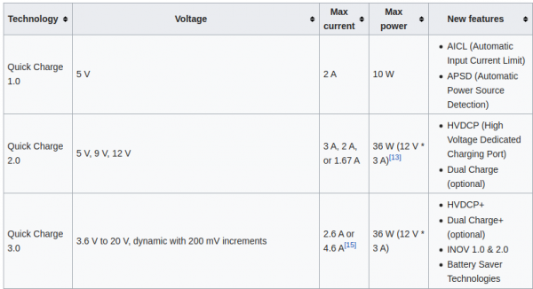
Quick Charge is a technology found in QualcommSoCs, used in devices such as mobile phones, for managing power delivered over USB. It offers more power and thus charges batteries in devices faster than standard USB rates allow. Quick Charge 2 onwards technology is primarily used for wall adaptors, but it is also implemented in car chargers and powerbanks (For both input and output power delivery).
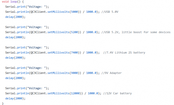
So in a nutshell: If you are able to speak the quick charge protocol, and with the right cable and power supply, you are able to get anything between 3.6 and 20V out of such a combination by just telling the power supply to do so.
This is great for maker projects in need of more power. There’s lots of things to consider and be cautious about.
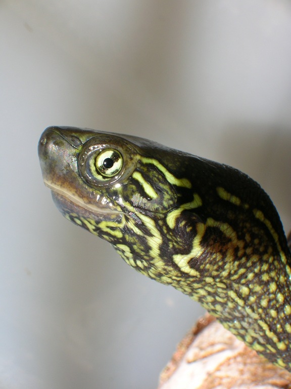
We’ve got several quite big fish tanks in our house. Mainly used by freshwater turtles.
say Hi! to Wilma.
These turtles need to be fed every once in a while. And while this is not an issue normally it’s an issue if you leave the house for travel for an extended period of time.
Of course there are humans checking on everything in the house regularly but as much as can be automated should and will be automated in our household. So the requirement wa to have the turtle feeding automated.
To achieve this is would be necessary to have a fixed amount of turtle food be dispensed into the tanks on a plan and with some checks in the background (like water quality and such).
It’s been quite a hassle to come up with a plan how the hardware should look like and work. And ultimately i’ve settled on retrofitting an off-the-shelf fish pond feeder to become controllable through MQTT.
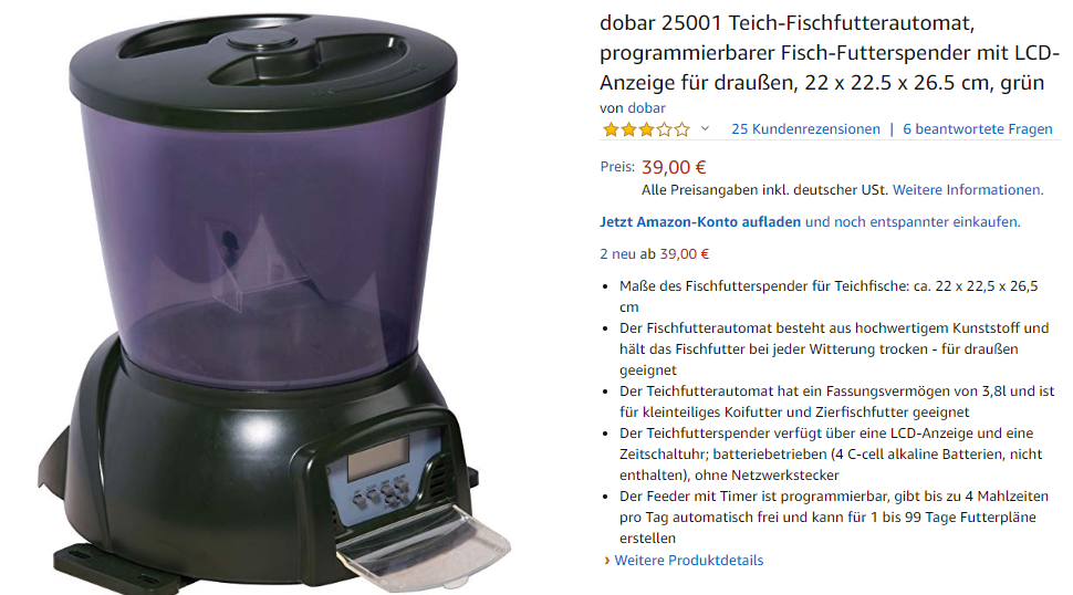
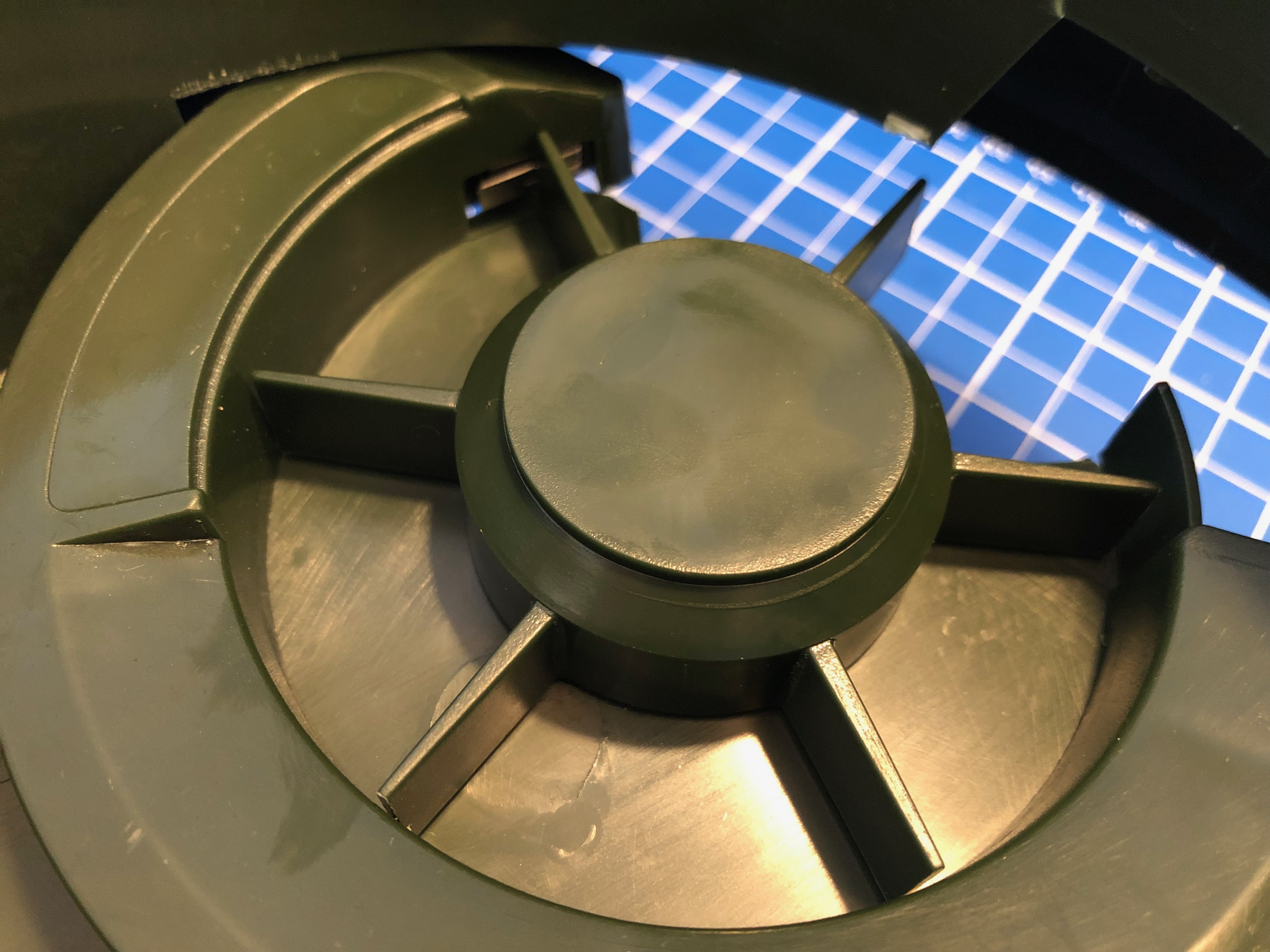
The pond feeder I’ve found and used is this one:
It’s not really worth linking to a specific product detail page as this sort of feeder is available under hundreds of different names. It always looks the same and is priced right around the same.
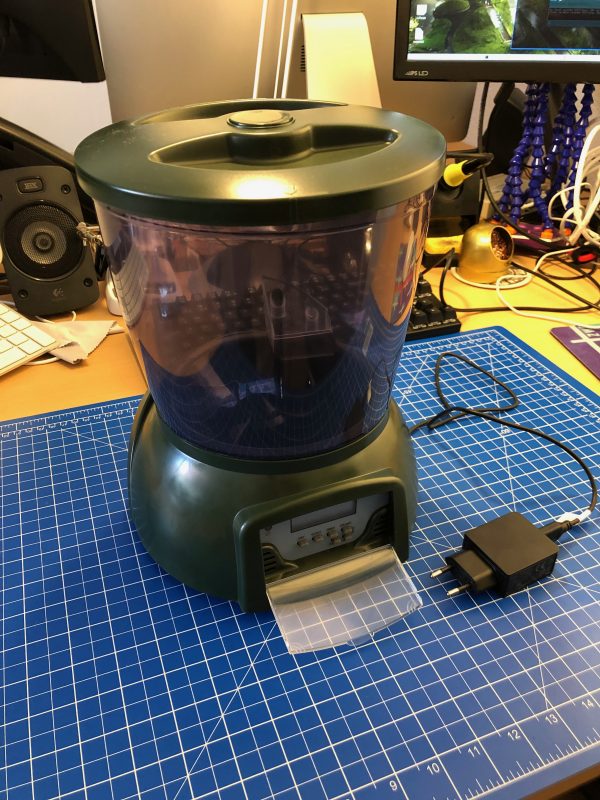
If you want to build this yourself, you want one that looks like the above. I’ve bought 3 of them and they all seem to come out of the same factory somewhere in China.
Anyway. If you got one you can easily open it up and start modifying it.
Hardware
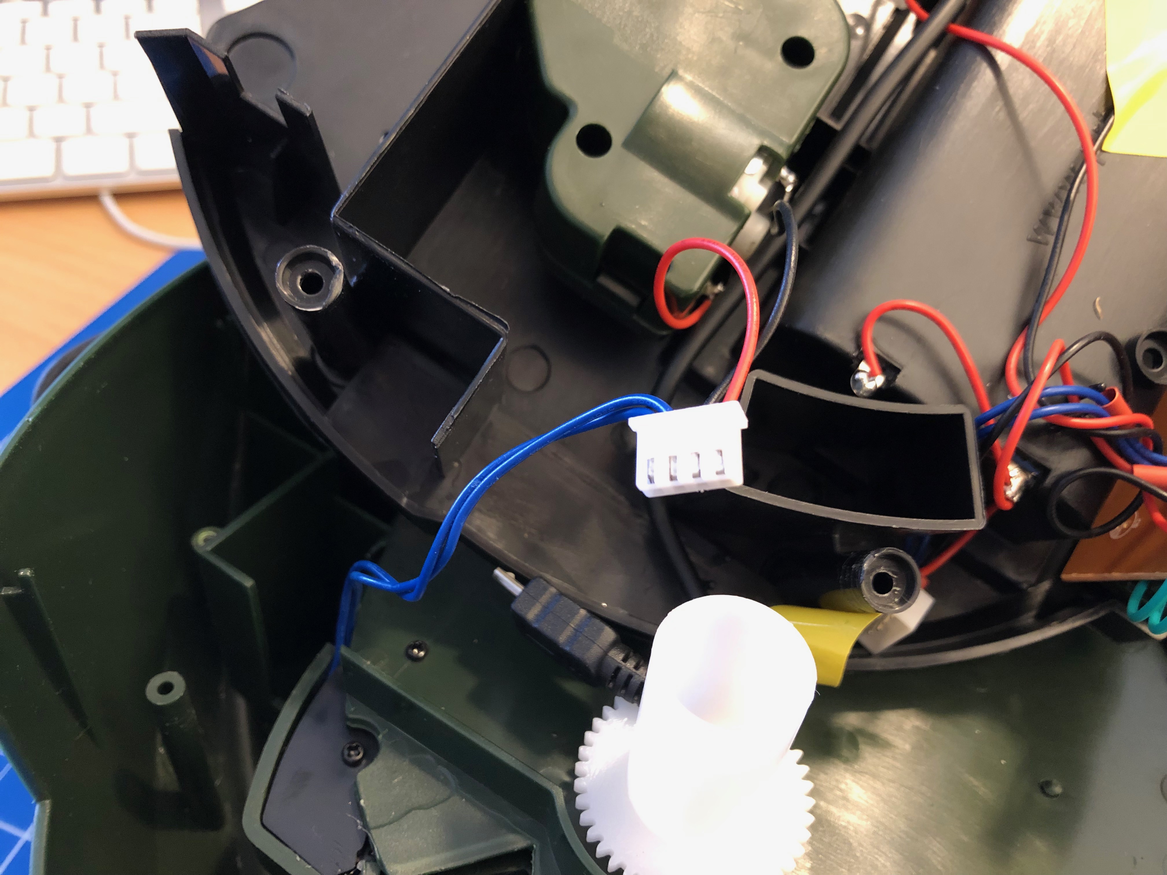
the wheel is turned by a DC motor and the switch is triggered by the wheels fins
I’ve added a connector to the switch and the motor cables for quick connect
The functional principle of the feeder is rather simple:
turn the feeder wheel
take the micro-switch status in account – when it’s pressed down the wheel must be pushing against it
turn it until the micro-switch is not pressed anymore
turn some more until it’s pressed again
Simple. Since the switch-status is not known on power loss / reboot a calibration run is necessary (even with the factory electronics) every time it boots up.
After opening the feeder I’ve cut the two cables going to the motor as well as the micro-switch cables. I’ve added a 4-Pin JST-XH connector to both ends. So I can reconnect it to original state if desired.
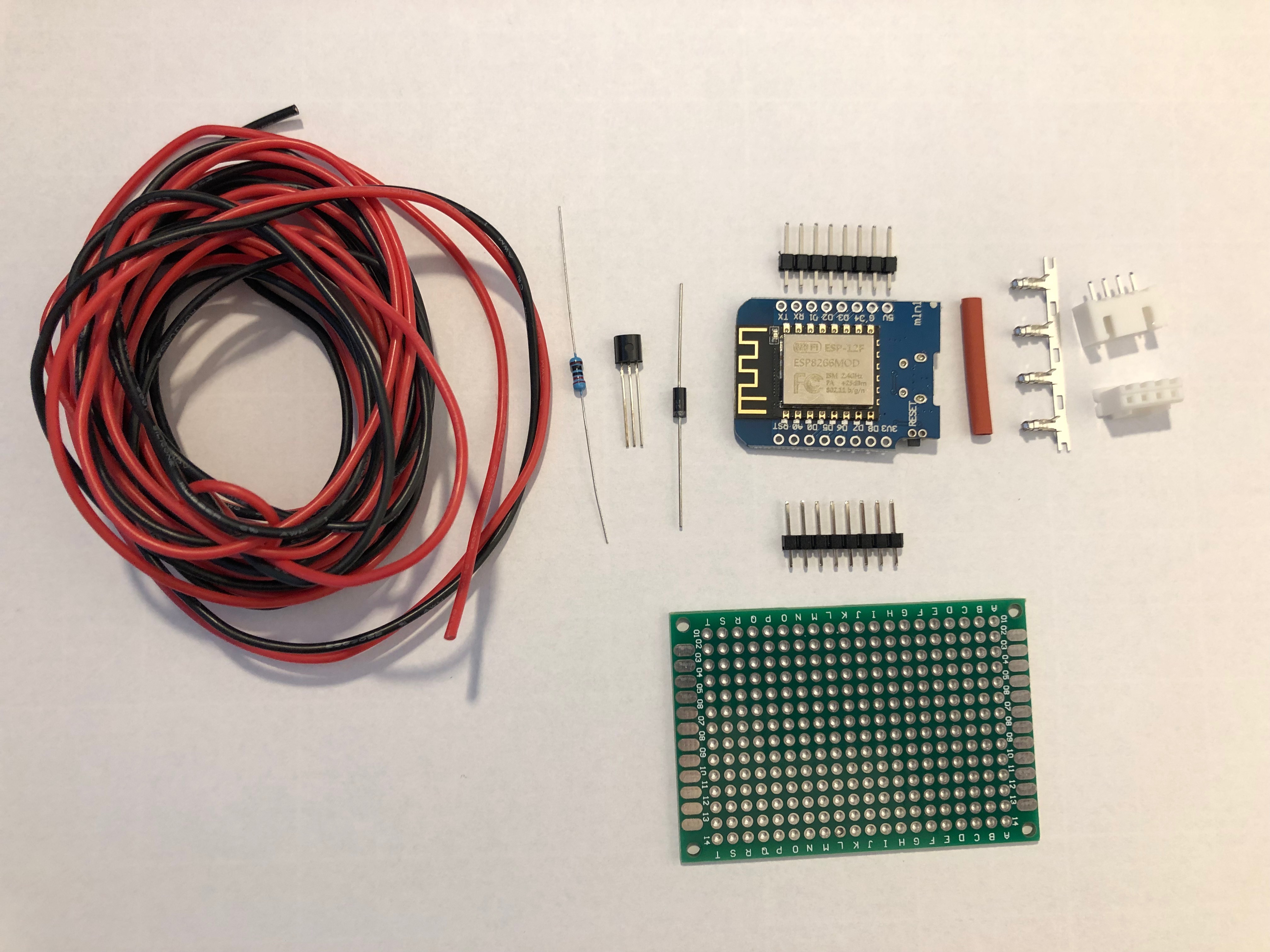
These are all the parts needed:
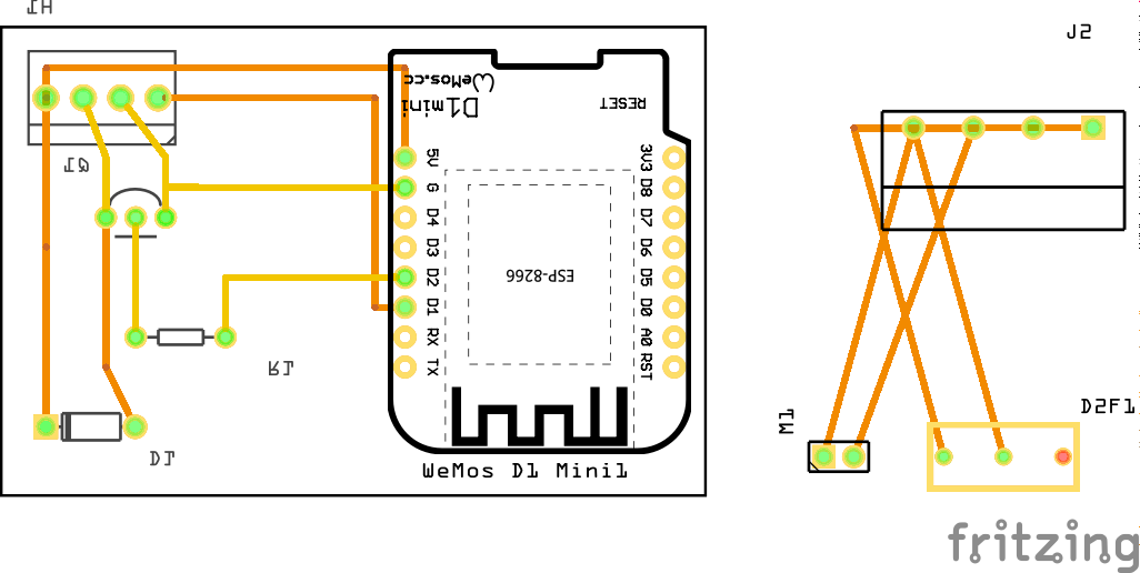
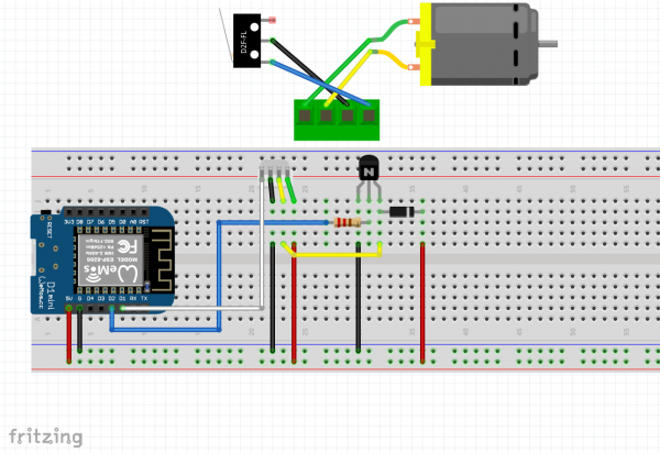
I am using a Wemos D1 Mini and a couple of additional components apart from the prototype board:
A PN2222 NPN transistor, a rectifier diode 1N4007 and a 220 Ohm resistor.
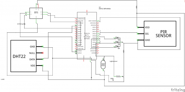
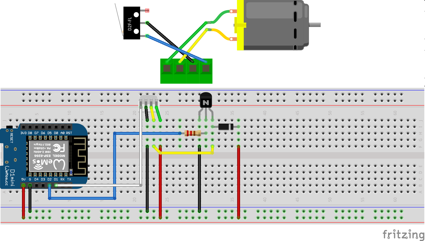
I’ve connected everything according to this schematic I’ve drawn with Fritzing:
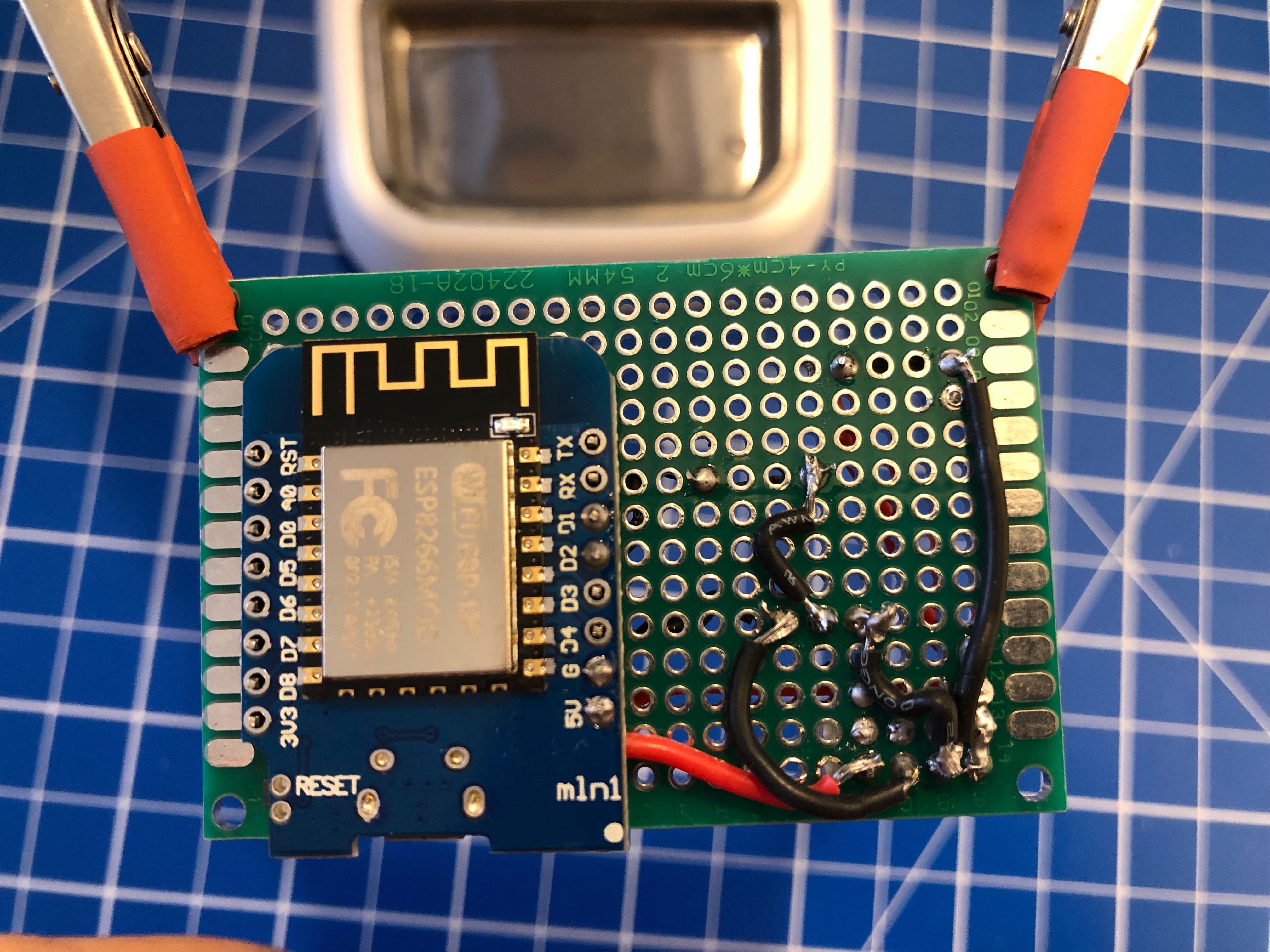
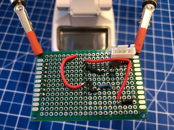
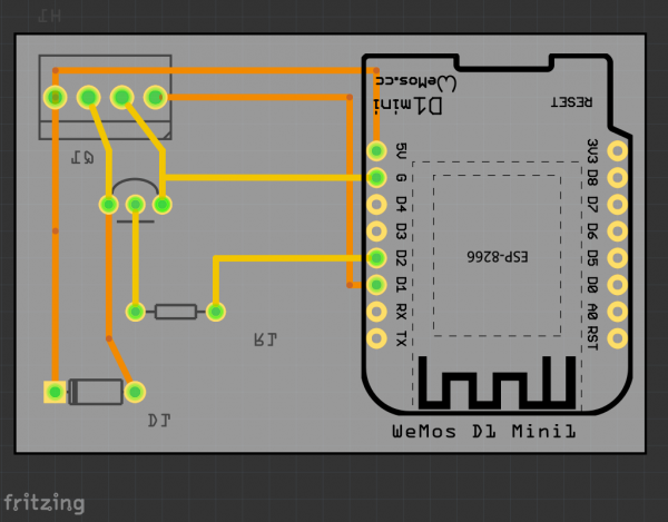
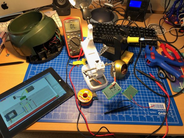
I’ve then prototyped away and put everything on the PCB. Of course with very limited solderig skill:
As you can see the JST-XH connector on Motor+Switch can now be connected easily to the PCB with all the parts.
Make sure you check polarity and that you did correctly hook up the motor and switch.
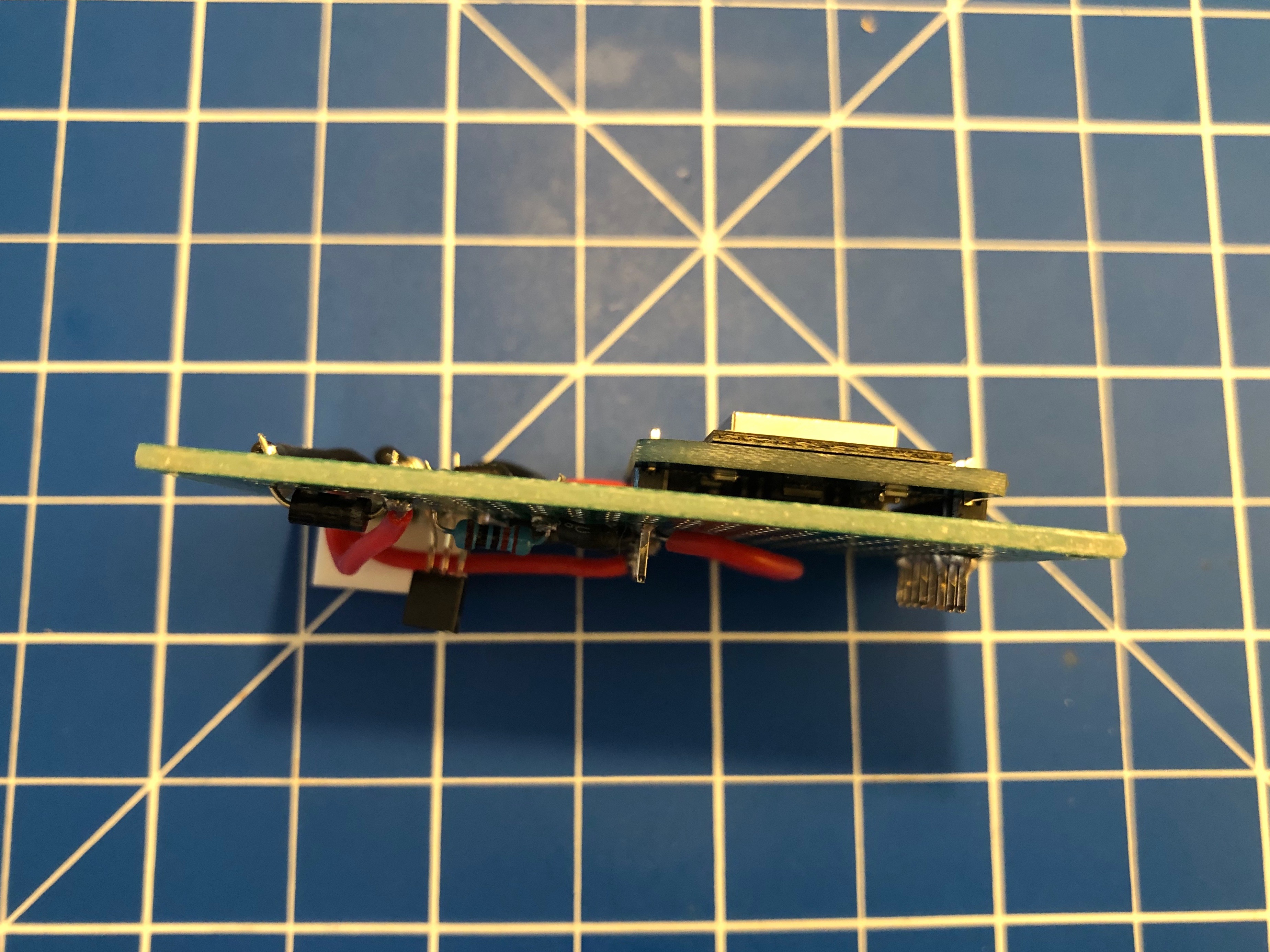
When done correctly the PCB (I’ve used 40mm x 60mm prototype pcb) and all cables will fit into the case. There’s plenty of room and I’ve put it to the side of it. I’ve also directly connected an USB cable to the USB port of the Wemos D1 Mini. As long as you put at least 1A into it it will all work.
Software
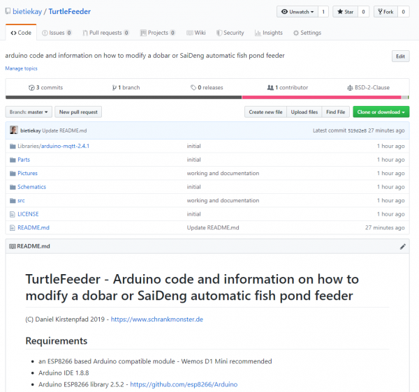
Since the Wemos D1 Mini sports an ESP8266 and is well supported by Arduino it was clear to me to use Arduino IDE for the software portion of this project.
To get everything running you need to modify the .ino file in the src folder like so:
Configuration
What you need to configure:
the output pins you have chosen – D1+D2 are pre-configured
WiFi SSID + PASS
MQTT Server (IP(+Username+PW))
MQTT Topic prefix
Commands that can be sent through mqtt to the /feed topic.
MQTT topics and control
There are overall two MQTT topics:
$prefix/feeder-$chipid/state This topic will hold the current state of the feeder. It will show a number starting from 0 up. When the feeder is ready it will be 0. When it’s currently feeding it will be 1 and up – counting down for every successfull turn done. There is an safety cut-off for the motor. If the motor is longer active than configured in the MaximumMotorRuntime variable it will shut-off by itself and set the state to -1.
$prefix/feeder-$chipid/feed This topic acts as the command topic to start / control the feeding process. If you want to start the process you would send the number of turns you want to happen. So 1 to 5 seems reasonable. The feeder will show the progress in the /state topic. You can update the amount any time to shorten / lengthen the process. On the very first feed request after initial power-up / reboot the feeder will do a calibration run. This is to make sure that all the wheels are in the right position to work flawlessly.
All in all there are 3 of these going to be running in our household and the feeding is going to be controlled either by Alexa voice commands or through Node-Red automation.
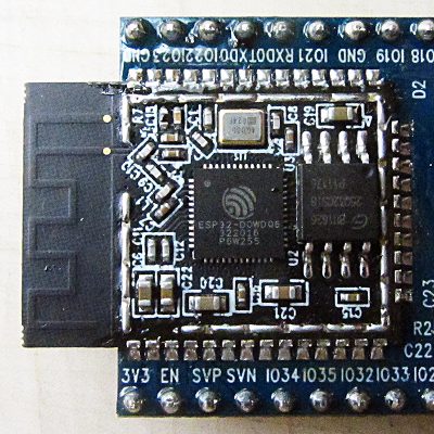
I had reported on my efforts to develop an indoor location tracking system previously. Back in 2017 when I started to work on this I only planned to utilize inexpensive EspressIf ESP32 SoCs to look for bluetooth beacons.
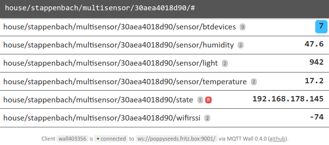
In the time between I figured that I could, and should, also utilize the multiple digital and analog input/output pins this specific SoC offers. And what better to utilize it with then a range of sensors that also now could feed their measurements into an MQTT feed along with the bluetooth details.
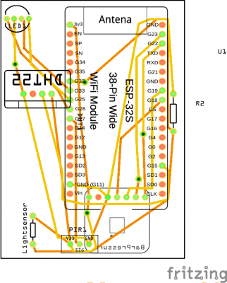
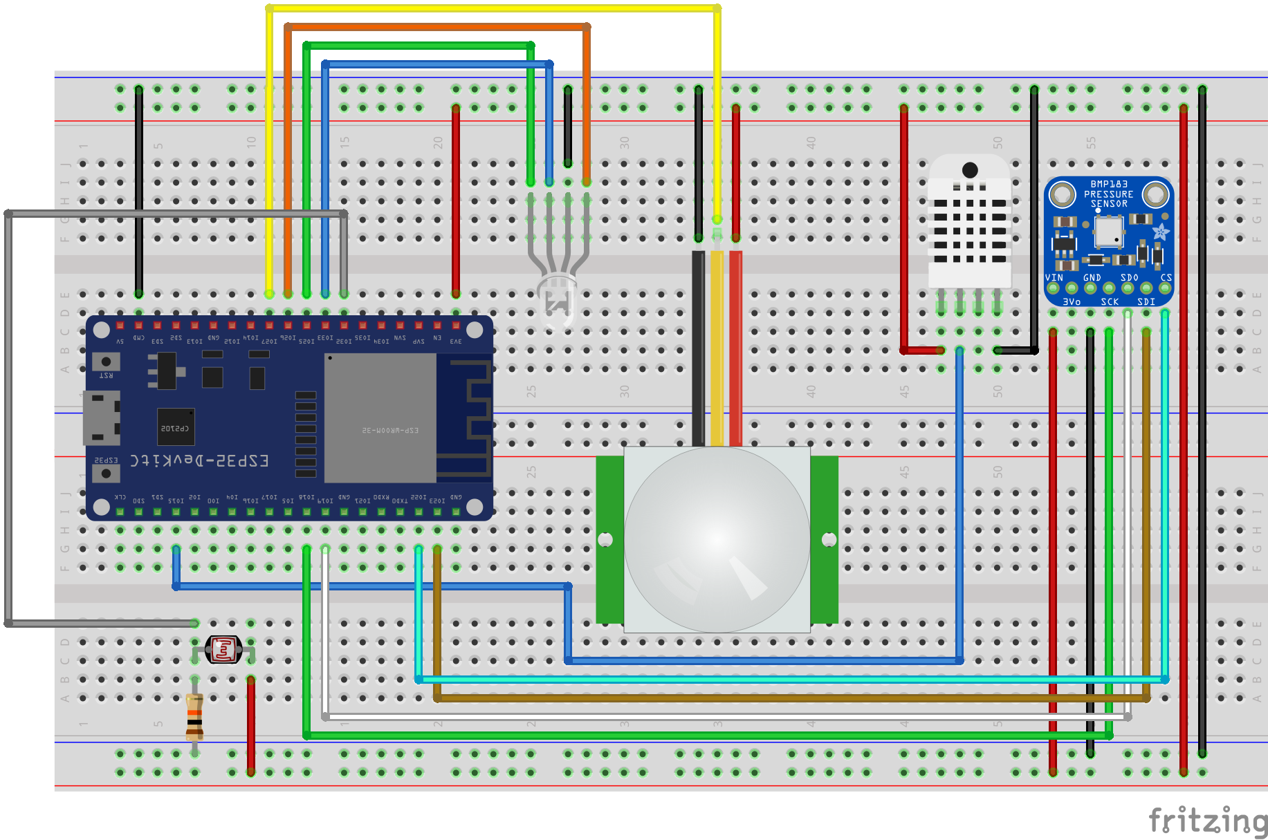
And there is a whole lot of sensors that I’ve added. On a breadboard it looks like this:
So what do we have here:
Motion sensor
Temperature sensor
Humidity sensor
Light sensor
Barometric pressure sensor
and of course an RGB LED to show a status
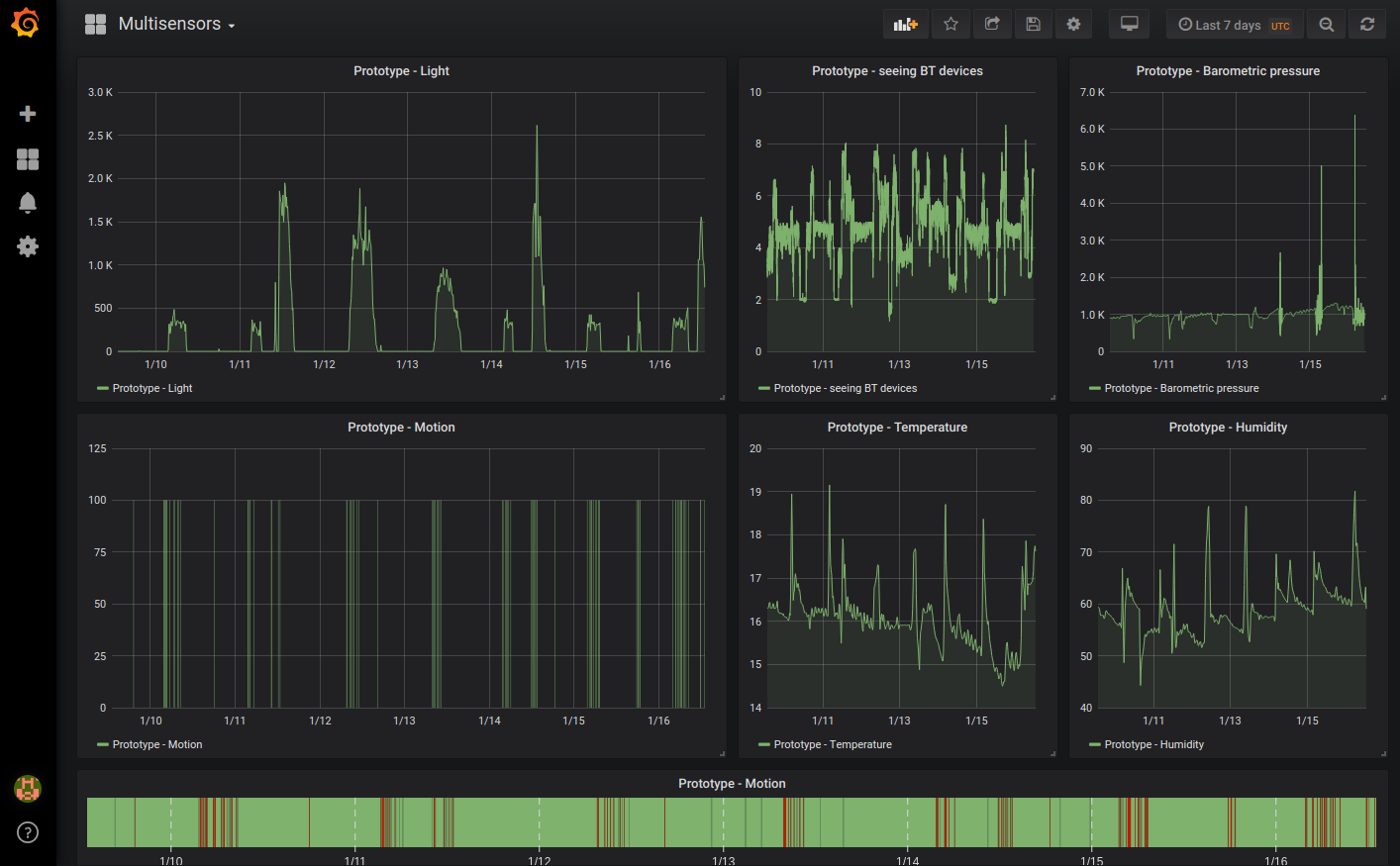
The software I’ve done already and after 3 weeks of extensive testing it seems that it’s stable. I will release this eventually later in the process.
I’ve also found plastic cases that fill fit this amount of sensory over the sensor cases I had already bought for the ESP32 alone. For now I’ll close this article with some pictures.