a self-built Bubble Bobble bartop arcade machine

I like playing arcade games. I’ve had an “arcade” in my home town and I used to go there after school quite frequently. It was a small place – maybe 5 machines and some pinball machines.

In february this year it occured to be that with the power of the Raspberry Pi and a distribution called RetroPie I could build something that would bring back the games and allow me to play/try those games I never could because my arcade was so small back in the days.

To get a better idea of how to approach this I started to search around and found the build-log of Holbrook Tech where they’ve built a “Bigger Bartop Arcade”.

With their basic plans I started drawing in Inkscape and told my father about the plan. He was immediately in – as the plan now was to not build one but two bartop arcade machines. He would take the task of carrying out the wood works and I would do the rest – procurements, electronics, wiring, design and “painting”.

first drawings of the side panels

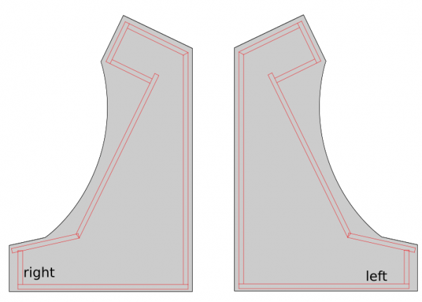
While I took the Holbrook Tech schematics as a base it quickly came apparent that I had to build/measure around the one fixed big thing in the middle: the screen.

screen

I wanted something decently sized that the RaspberryPi would be able to push out to and that would require no maintenance/further actions when installed.

To find something that fits I had my requirements fixed:

  • between 24″ – 32″
  • colour shift free wide viewing angle
  • 1080p
  • takes audio over HDMI and is able to push it out through headphone jack

I eventually settled for a BenQ GW2780 27″ monitor with all boxes ticked for a reasonable price.

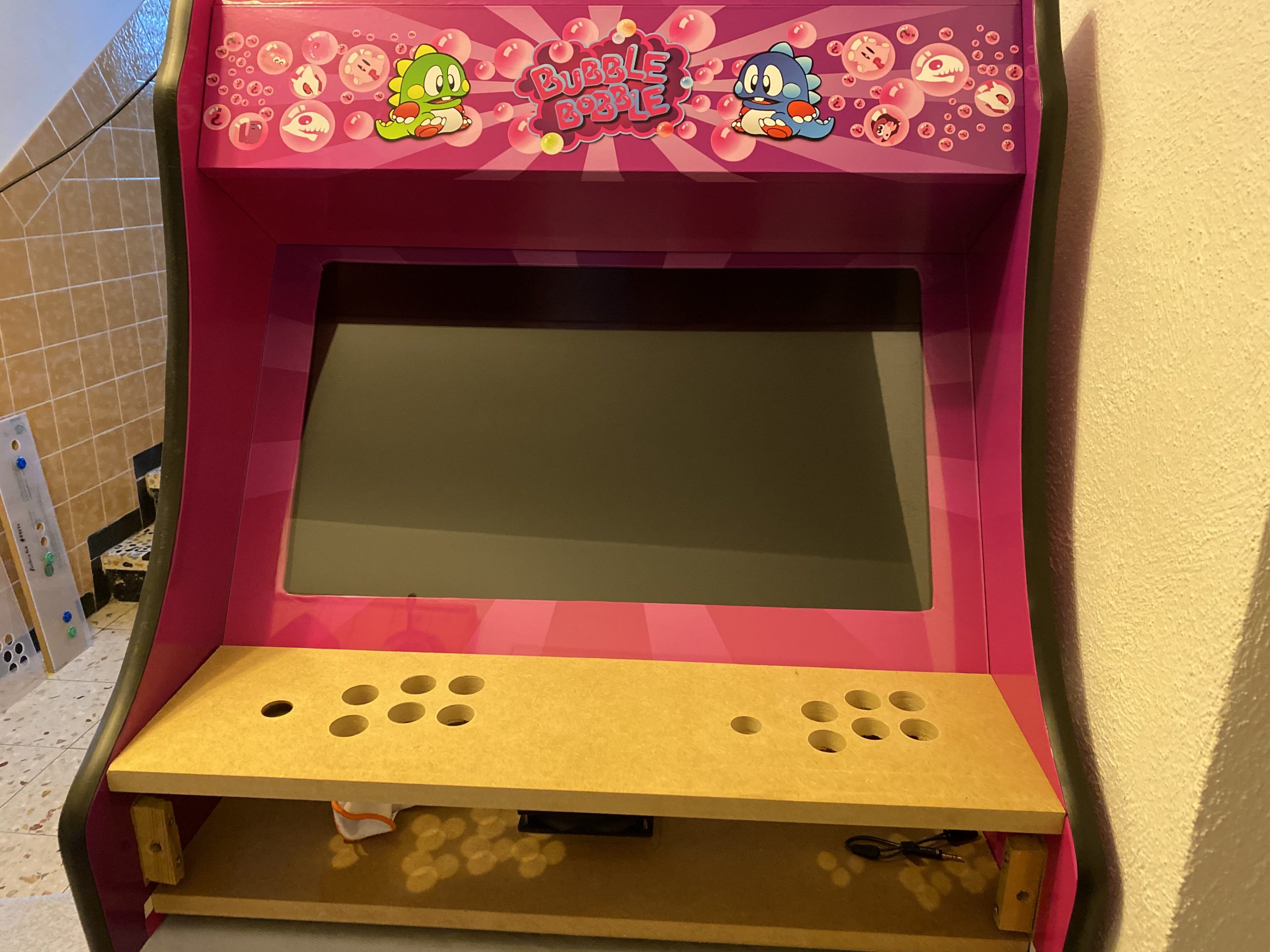
After the monitor arrived I carried it to my fathers house and we started to cut the bezel as a first try.

measuring the monitor in – on a piece of wood for testing.

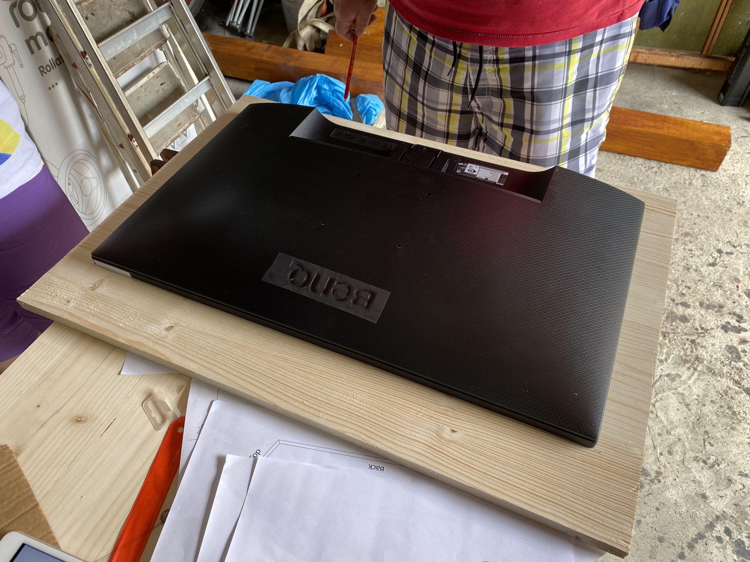
After some testing with plywood we went for MDF as it was proposed by others on the internet as well. This made the cutting so much easier.

woodwork

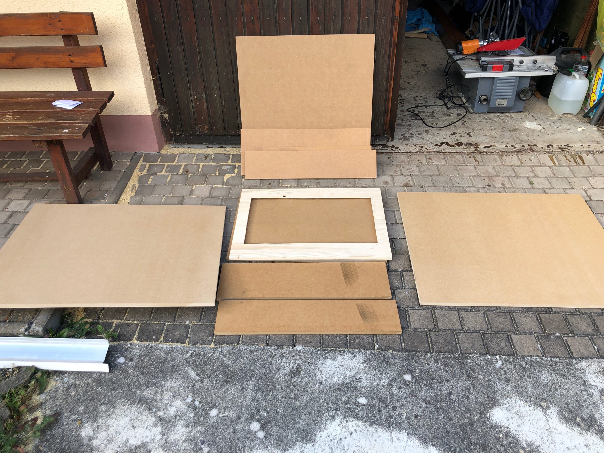
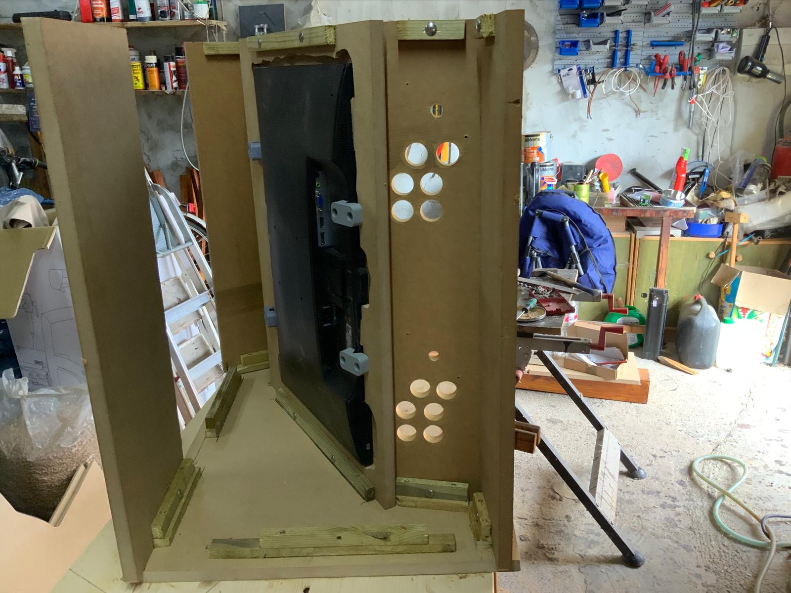
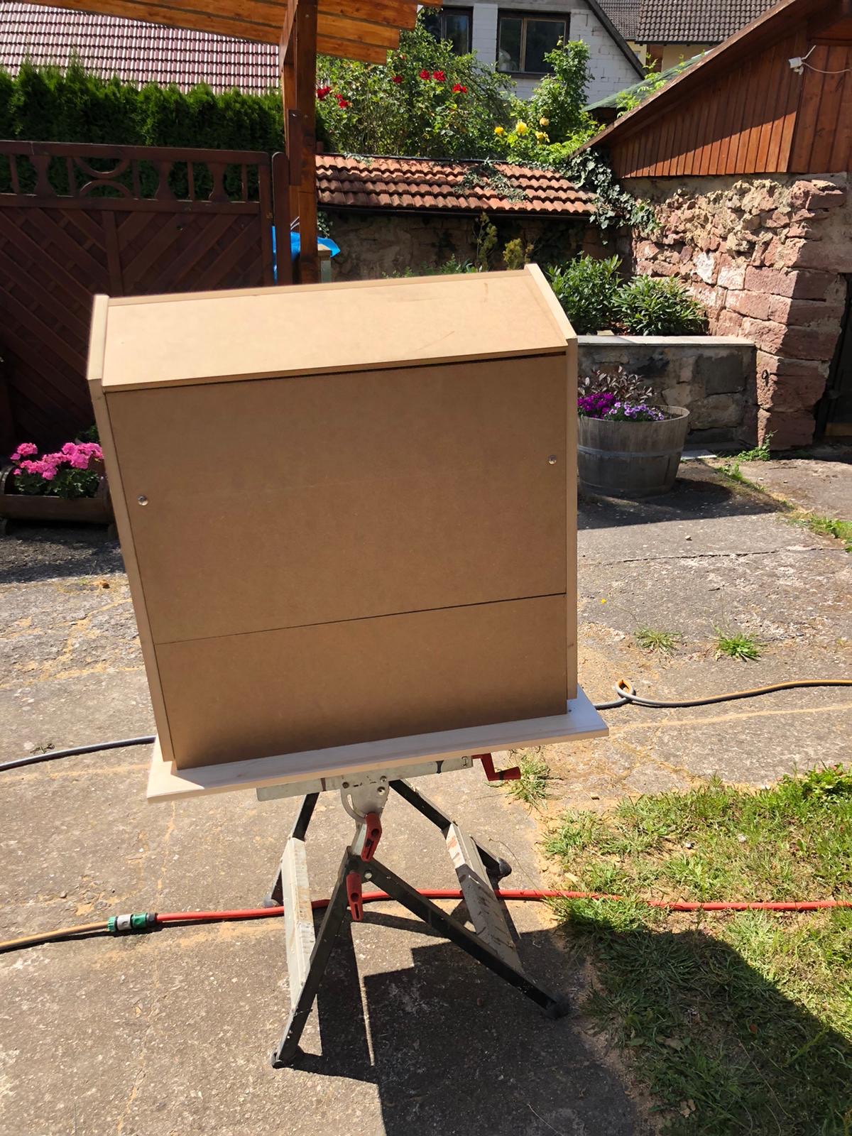
We went with standard 2cm MDF sheets and my father cut them to size with the measurements derived from the monitor bezel centerpiece.

Big thanks to my father for cutting so much wood so diligently! The next days he sent me pictures of what he’d made:

the plywood bezel was replaced with the MDF version
Each sheet of MDF wood got a steel screw thread insert. The screw is going on the inside through another peice of wood which is screwed and glued directly to the insides. This holds everything firm and is invisible from the outsides.
The only screws visible from the outside are holding the back panel on. Because you need to be able to remove the back panel they can be removed. Also the back panel is plit into two parts because that gave more structural strength and helps with the power input mounting later.
I went for Joystick + 6-Button layout for the control panel. I’ve changed the measurements a bit over the ones I’ve found on the internet to my taste.
The above schematics show the actual measured holes as they were drilled. As everything went more or less “free-hand” it’s quite astonishing to me how accurate it went. This measurement schematic was later used to laser cut the acrylic handrest.

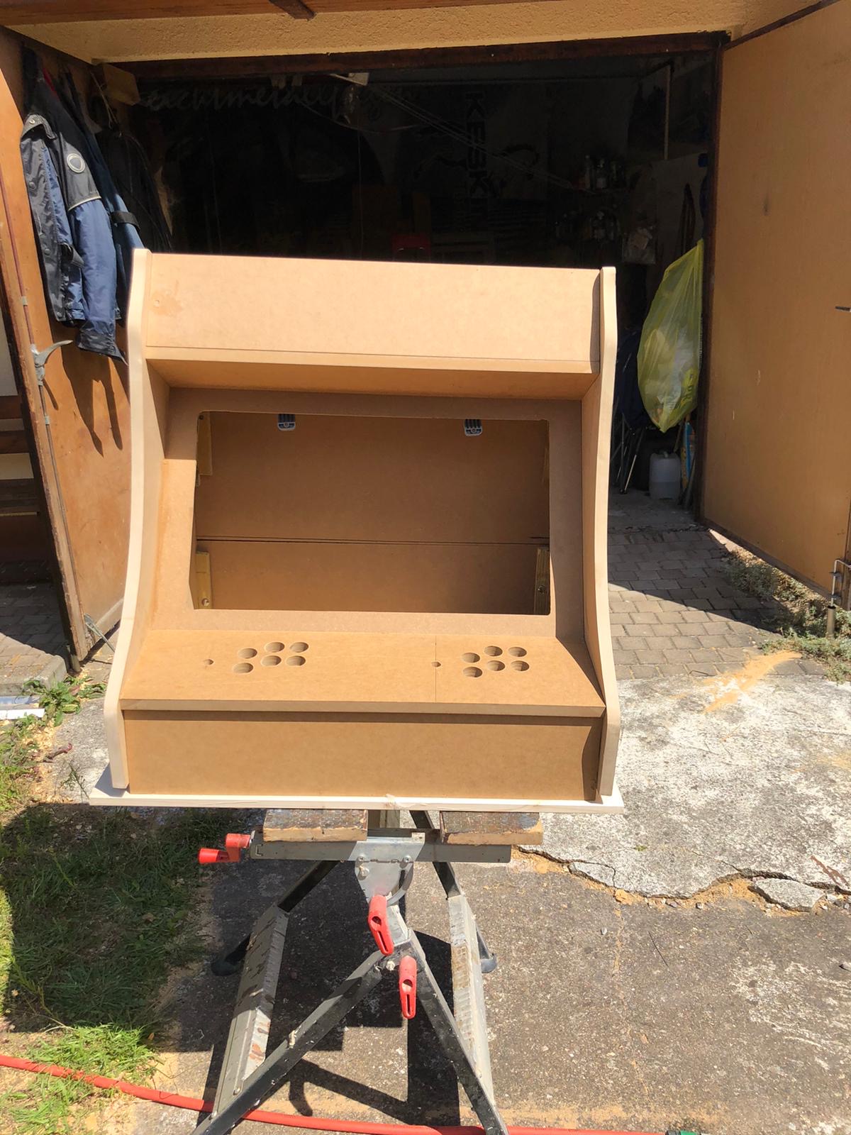
The side panels got a cut around for the black T-Molding to be added later.

electronics and wiring

After about 2 weeks my father had built the first arcade out of sheets of MDF and I had taken delivery of the remaining pieces of hardware I had ordered after making a long list.

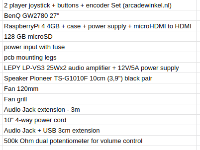
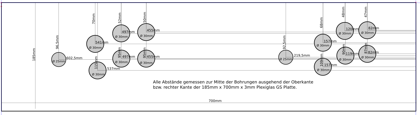
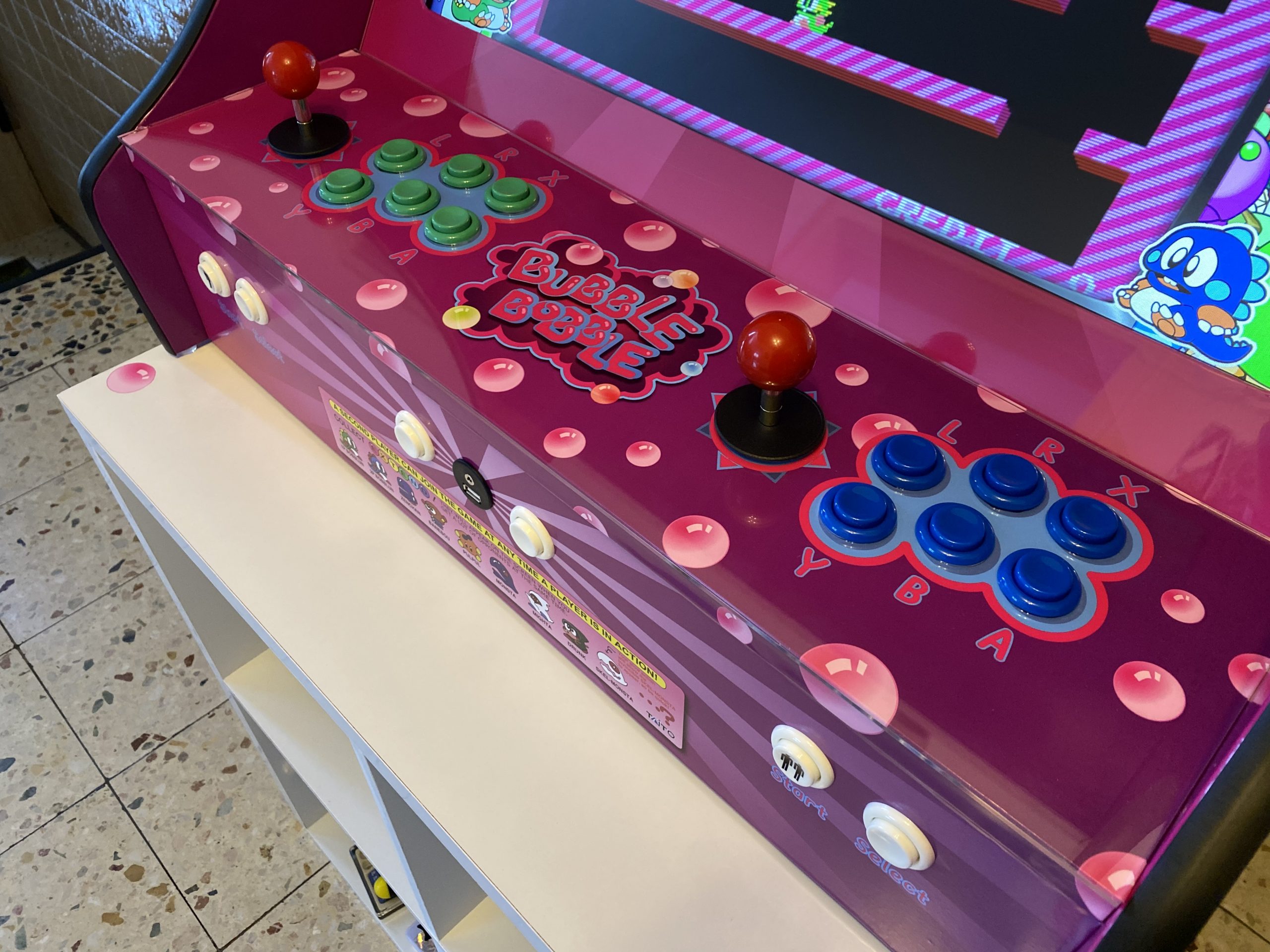
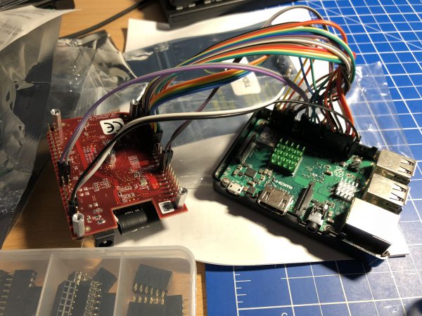
The most interesting parts of the above list might be the 2-player joystick + buttons + encoder set.

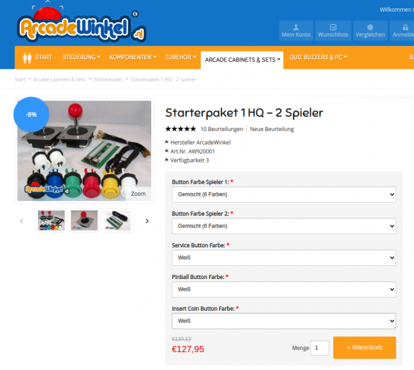
It contains 2 standard 4/8-way switchable arcade joysticks, 10 buttons, all microswitches required and the Ultimarc I-PAC-2 joystick encoder.

You connect every microswitch to this board and it will translate all button presses/joystick movements into keyboard or joystick movements. You connect it through USB to the RaspberryPi and it either shows up as 2 gamepads or one keyboard. Also a nice configuration app is available from the manufacturer.

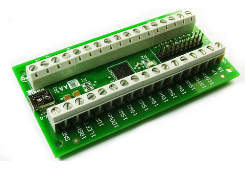
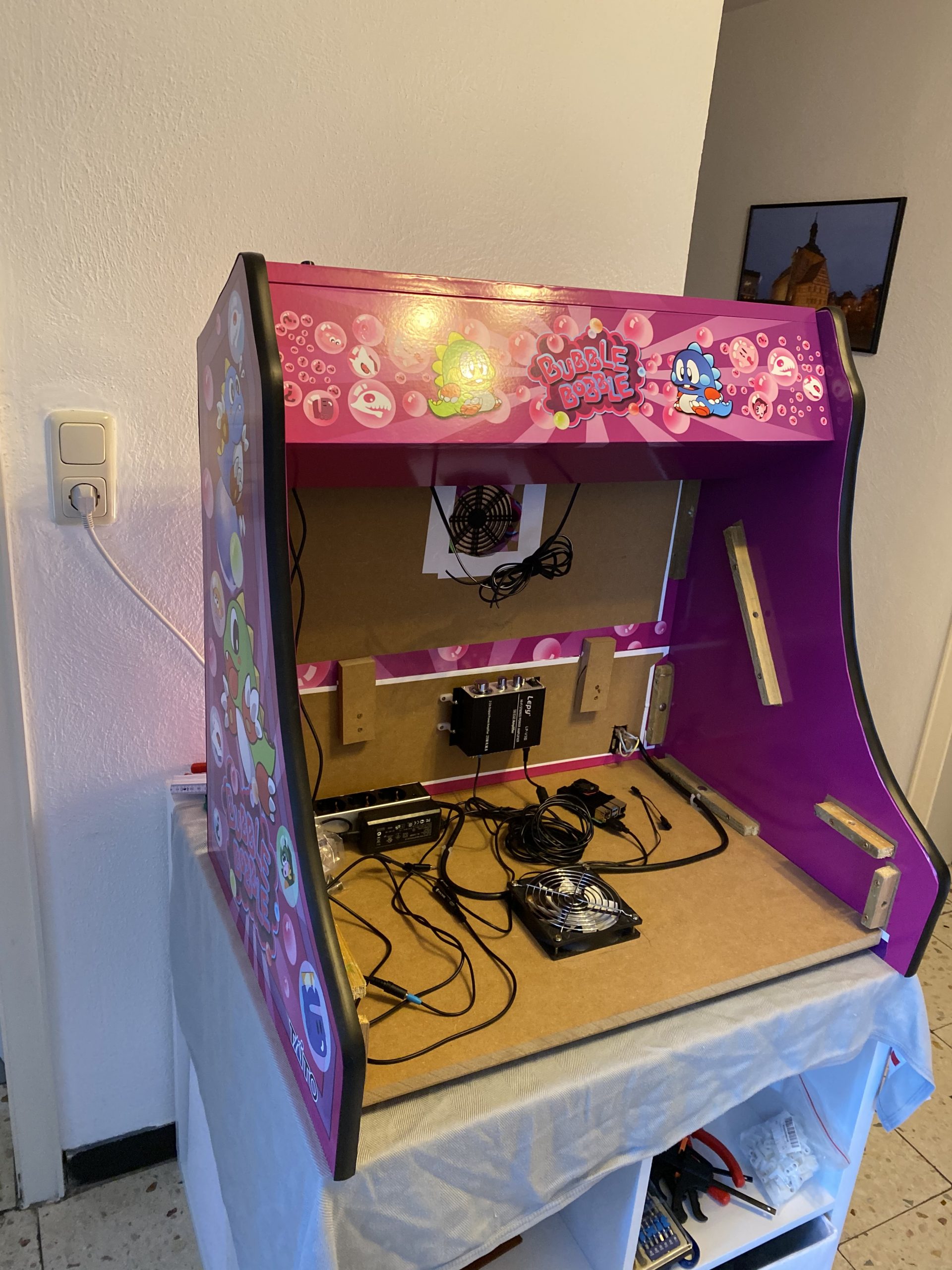
So when I got the first arcade from my father I started to put in the electonics immediately.

The wiring to the I-PAC was straight forward. Worked at the first try.

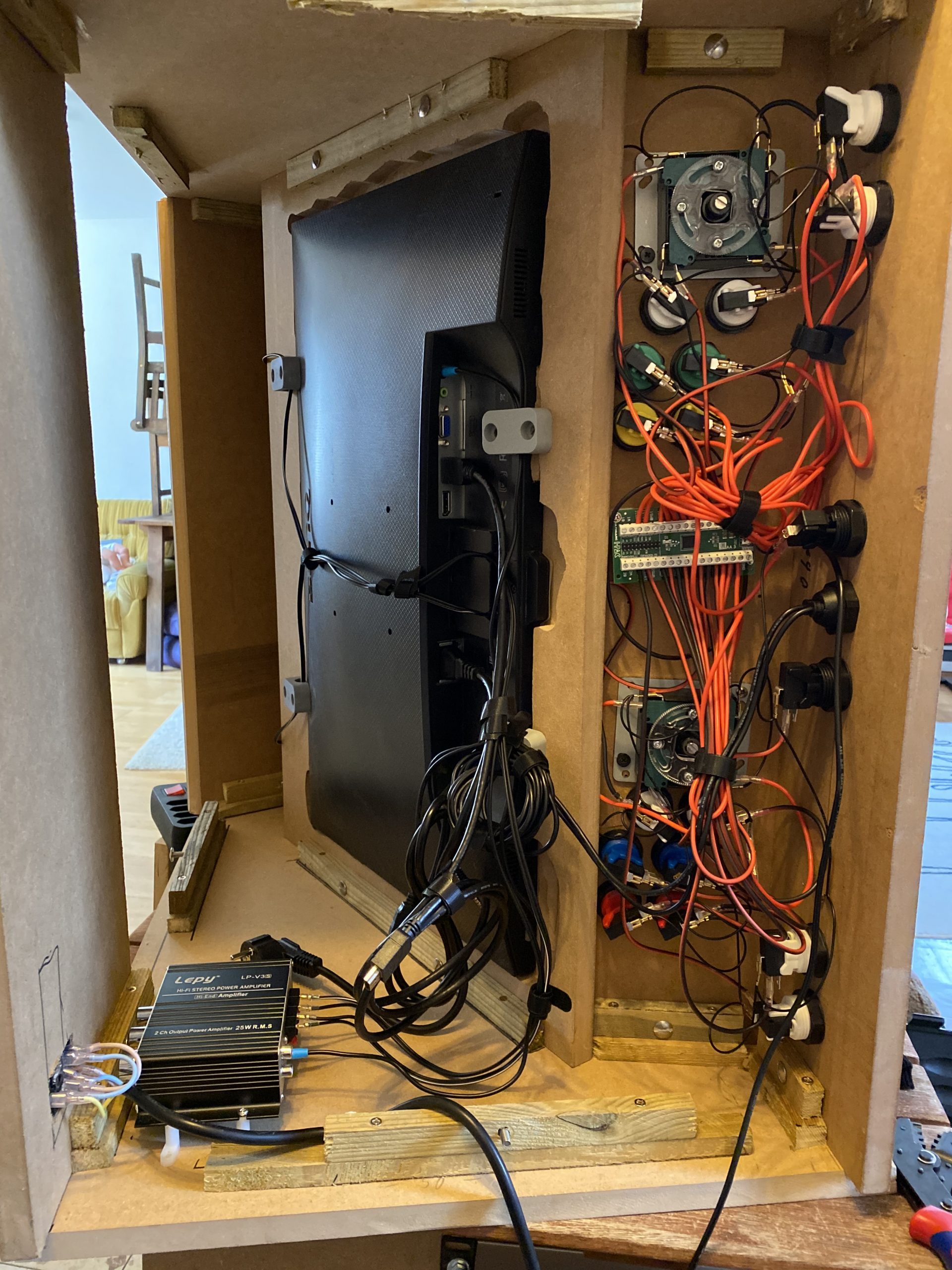
The sound was a bit more complicated. I wanted a volume control knob on the outside but also did not want to disassemble any audio amplifier.

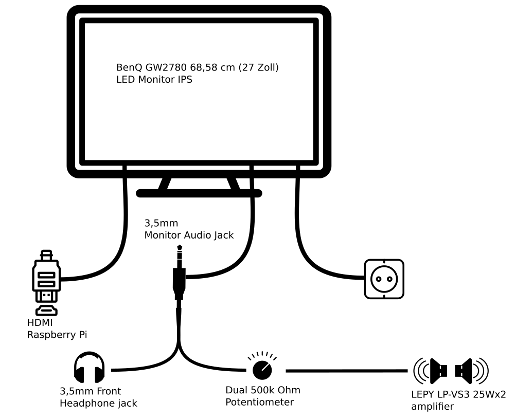
I went with the simplest solution: A 500k Ohm dual potentiometer soldered into the headphone extension cable going to the amplifier. The potentiometer then got put into a pot and a whole made it stick out so that a knob could be attached.

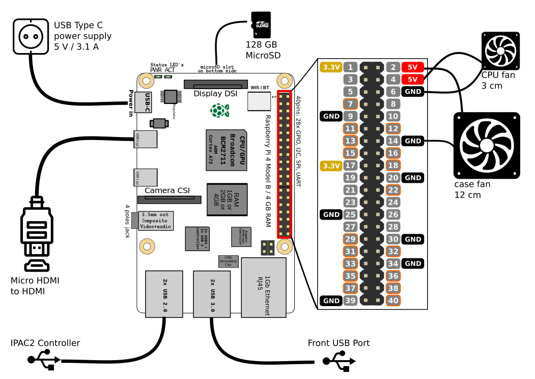
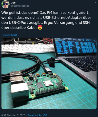
The RaspberryPi set-up then only lacked cooling. The plan was to put a 120mm case fan to pull in air from the bottom and went it out another 120mm case hole at the upper back. Additionally the RaspberryPi would get it’s own small 30mm fan on top of it’s heatsink case.

I attached both fans directly to the RaspberryPi – so I saved myself another power supply.

software

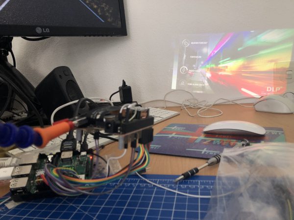
Now I had to make it all work together. As I wanted to use RetroPie in the newest 4.6 release I’ve set that up and hooked it all up.

On first start-up EmulationStation asked me to configure the inputs. It had detected 2 gamepads as I had put the IPAC-2 into gamepad mode before. You can do this with a simple mode-switch key-combination that you need to hold for 10 seconds to make it switch.

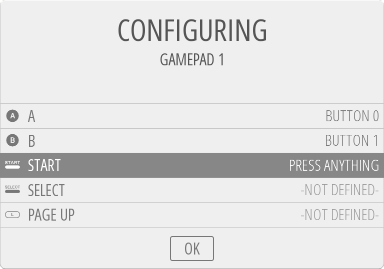
The configuration of the buttons of the two players went without any issue. First I had set-up the player 1 input. Then I re-ran the input configuration again for player 2 inputs.

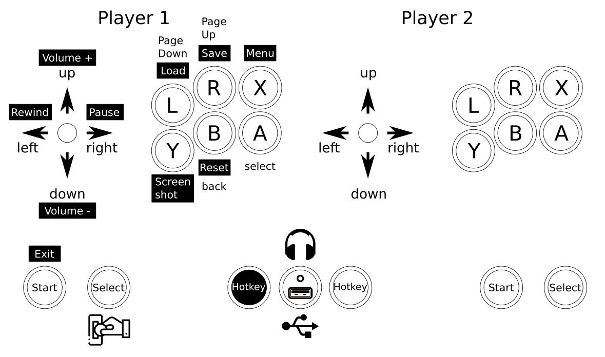
The controls where straight forward. I wanted mainly 4-way games but with enough buttons to switch to some beat-em-ups at will.

So I configured a simple layout into Retroarch with some additional hotkeys added:
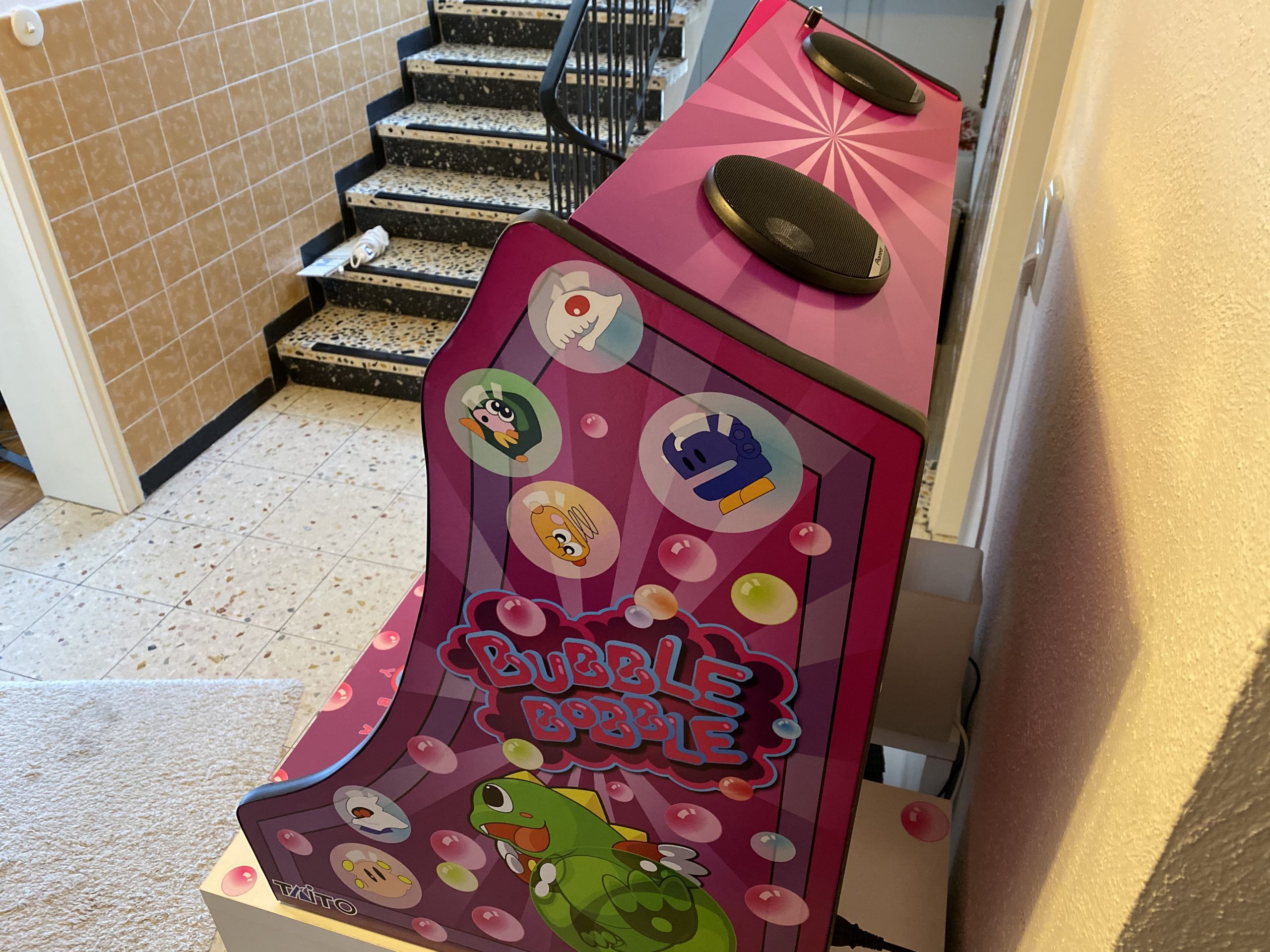
vinyl design

I tossed around several design ideas I had. Obviously derived from those games I wanted to play and looked forward to.

There was some Metal Slug or some Cave shooter related designs I thought of. But then my wife had the best ideas of them all: Bubble Bobble!

So I went and looked for inspiration on Bubble Bobble and found some but none that sticked.

There was one a good inspiration. And I went to design based upon this one – just with a more intense purple color scheme.

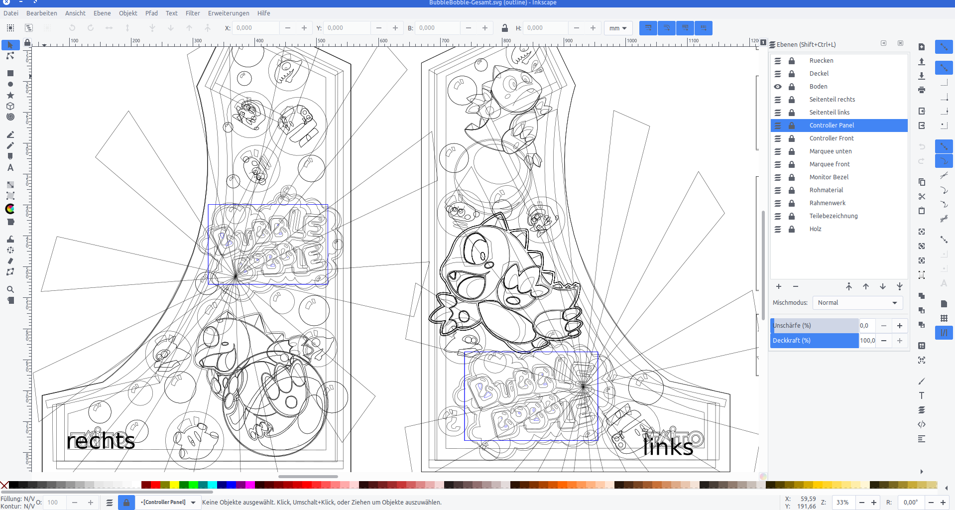
I used Inkscape to pull in bitmap graphics from Bubble Bobble and to vectorize them one by one, eventually ending up with a lot of layers of nice scalable vector graphics.

With all design set I went and sliced it up and found a company that would print my design on vinyl.

With the final arcade-wood accessible top me I could take actual measurements and add to each element 4cm of margin. This way putting it on would hopefully be easier (it was!).

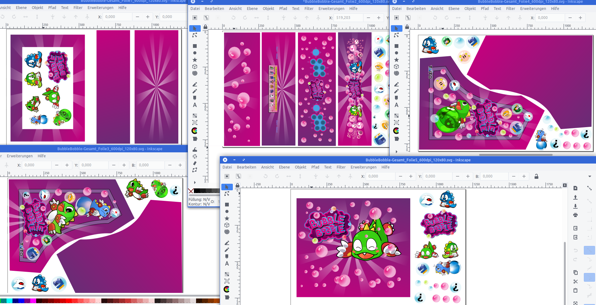
Originally I wanted to have it printed on a 4m by 1,2m sheet of vinyl. It all would have fit there.

But I had to find out that Inkscape was not capable of exporting pixel data at this size and a pixel-density of 600dpi. It just was too large for it to output.

So I had to eventually cut all down into 5 pieces of 1,2m by 80cm each.

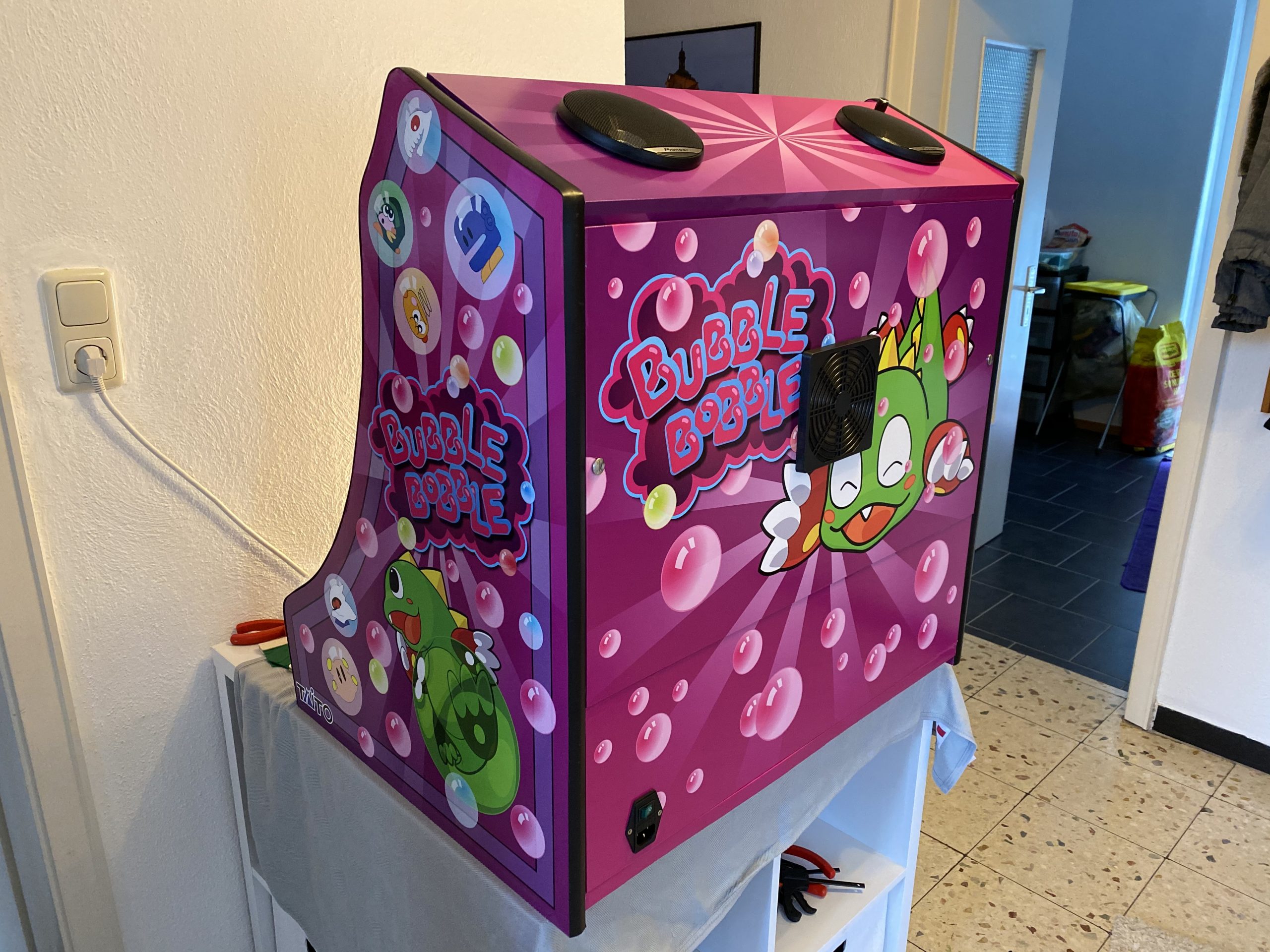
After about 7 days all arrived printed on vinyl at my house. I immediately laid everything out and tried if it would fit. It did!

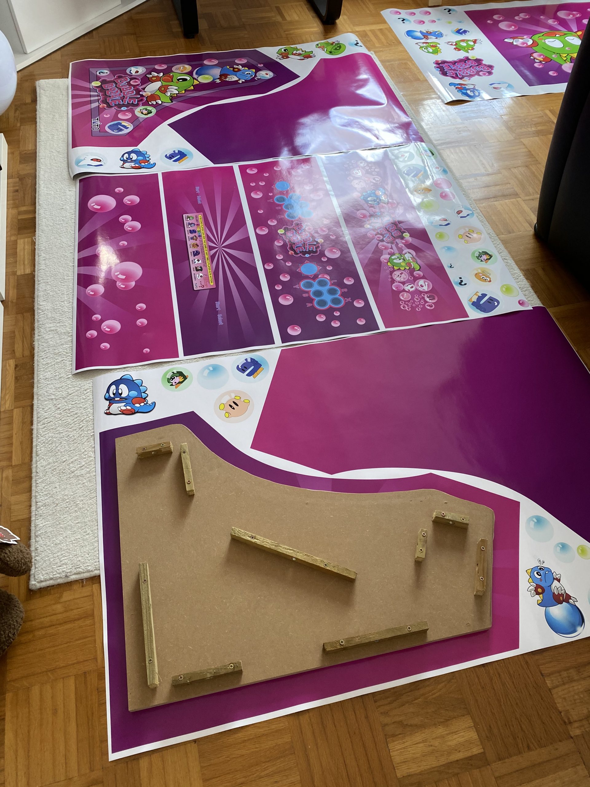
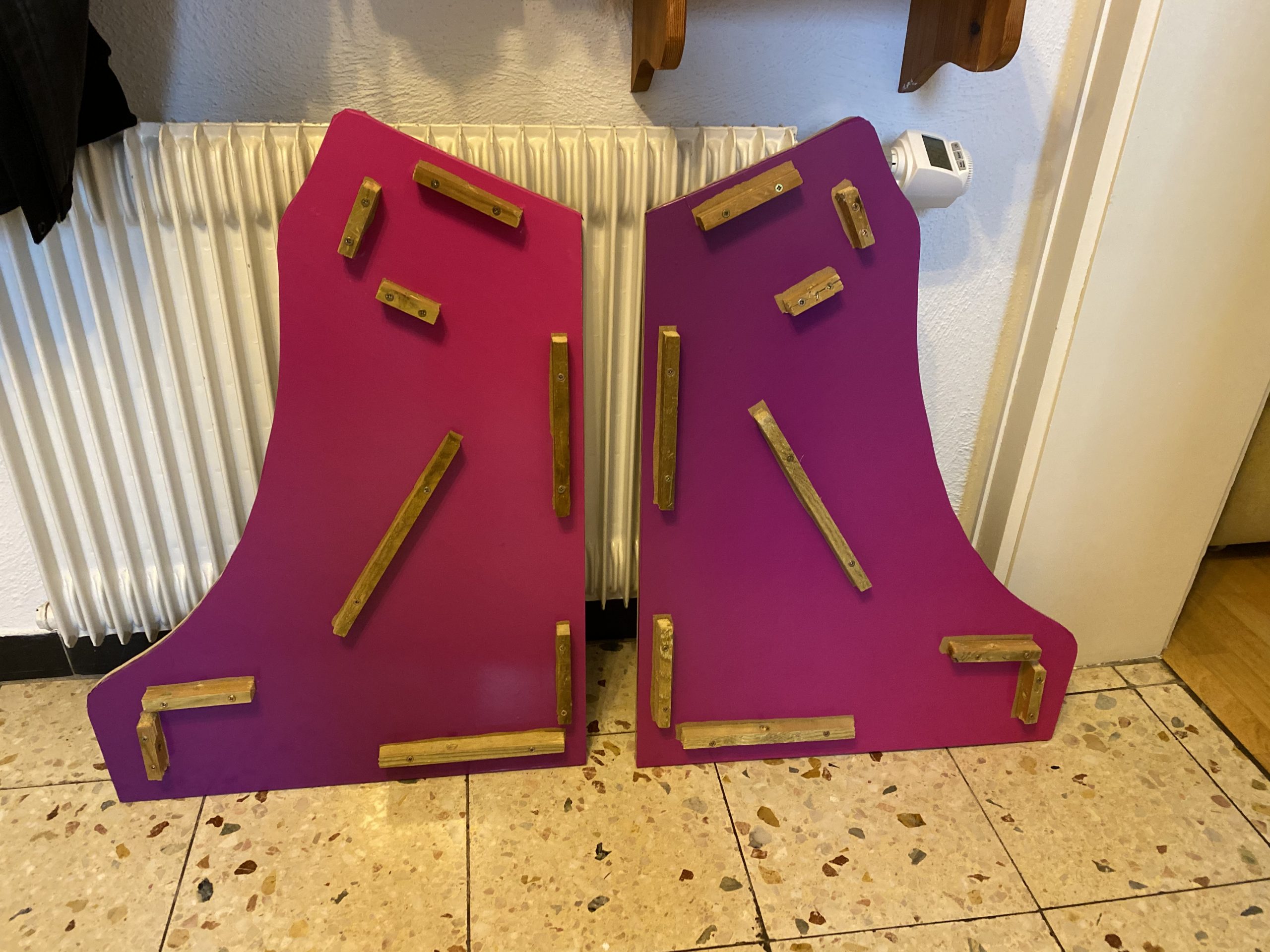
Now everything had to go onto the wood. I did a test run before ordering to check if it would stick securely to the wood. It did stick very nicely. So putting it on was some intense fiddling but it eventually worked out really really great.

You can see the inside here and the structural struts where everything attaches to screwed in from the insides.

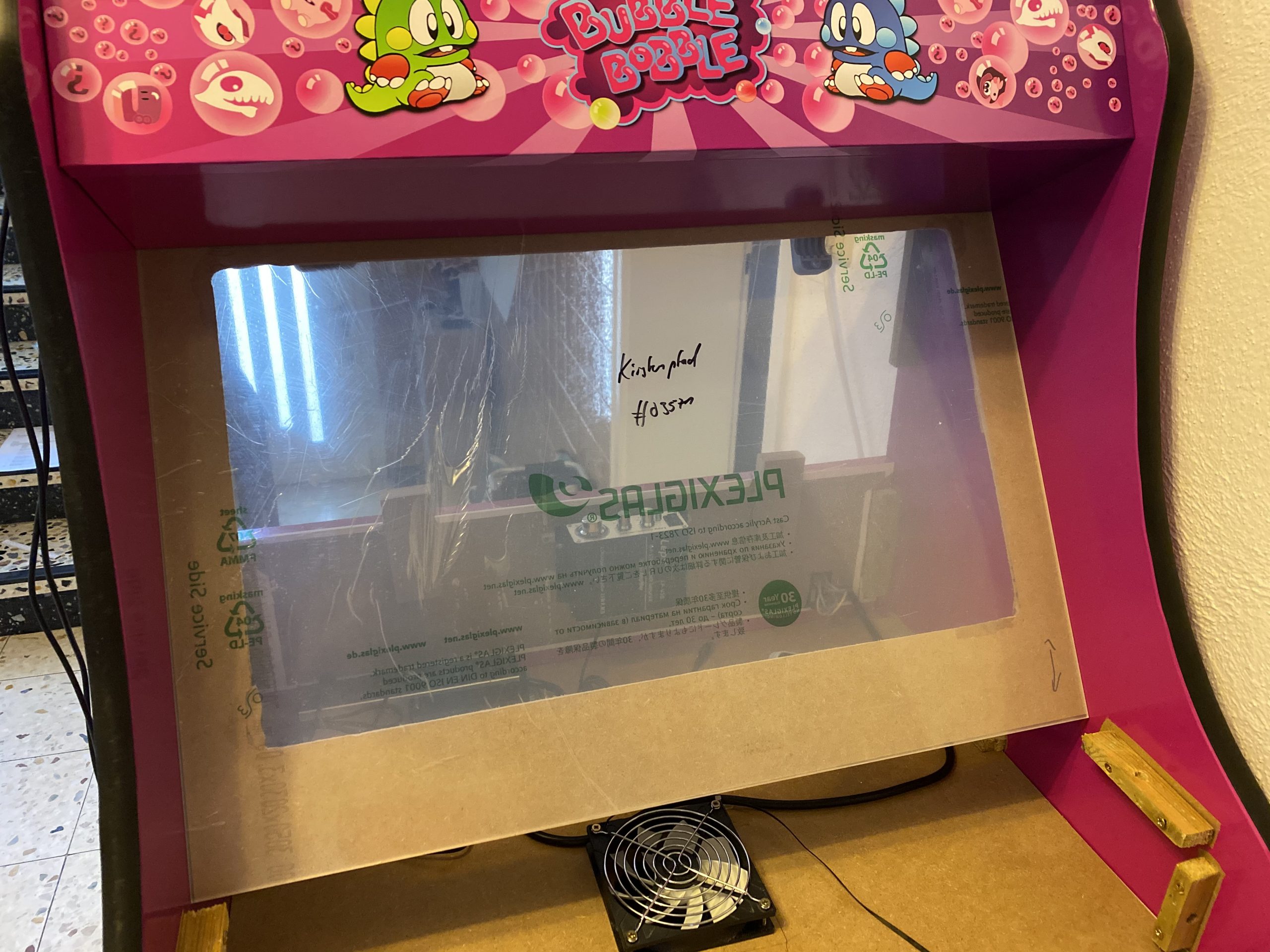
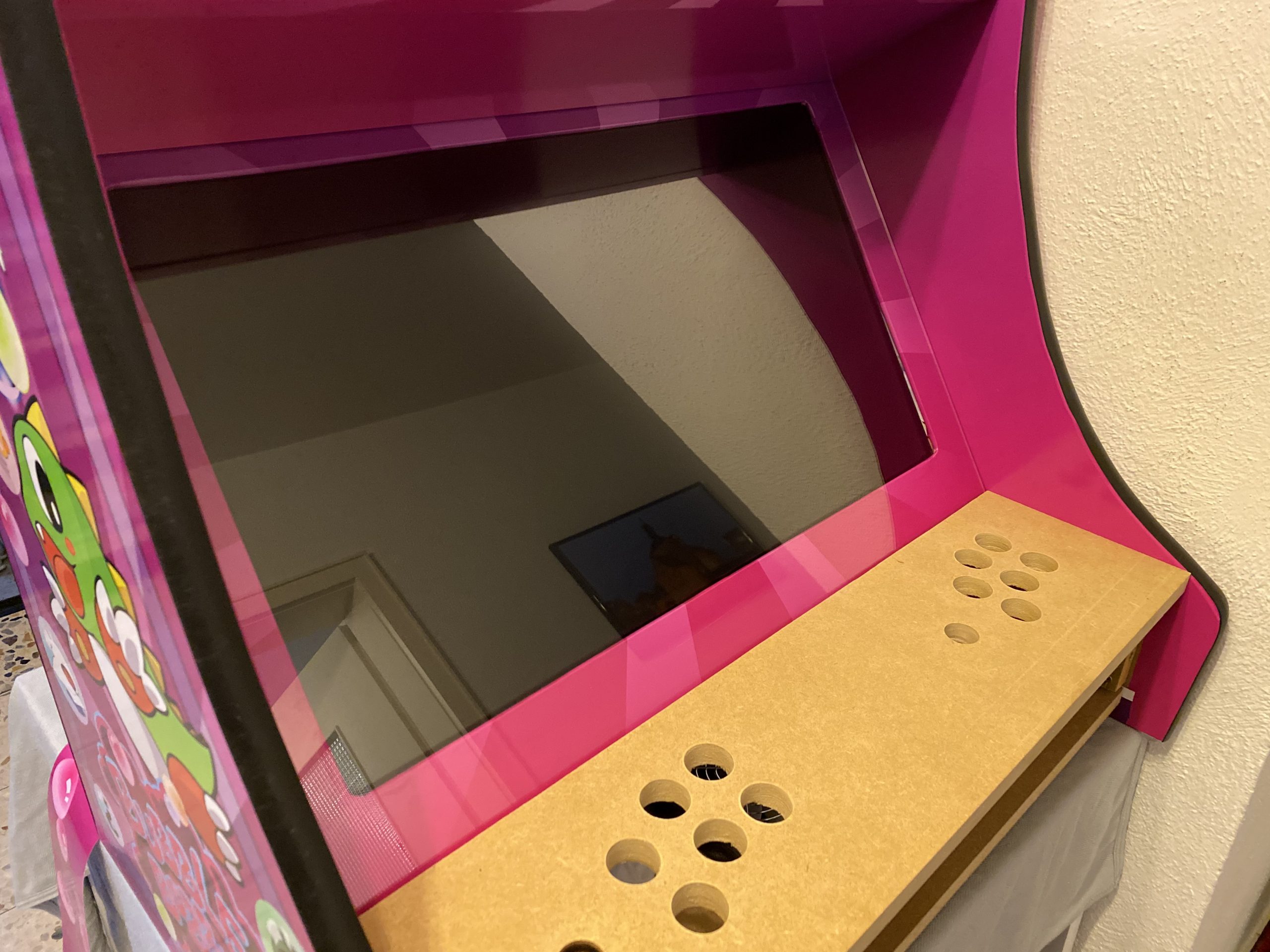
Now it was time for some acrylic. I wanted to get a good bezel and covering of the monitor as well as the handrest and the front buttons.

Cutting acrylic myself was out of questions – so I went with a local company that would laser-cut acrylic for me to my specification.

I’ve sent them the schematics and measurements and the panels for reference and 4 days later the acrylic arrived. We could then put the last bits together for completion!

Result

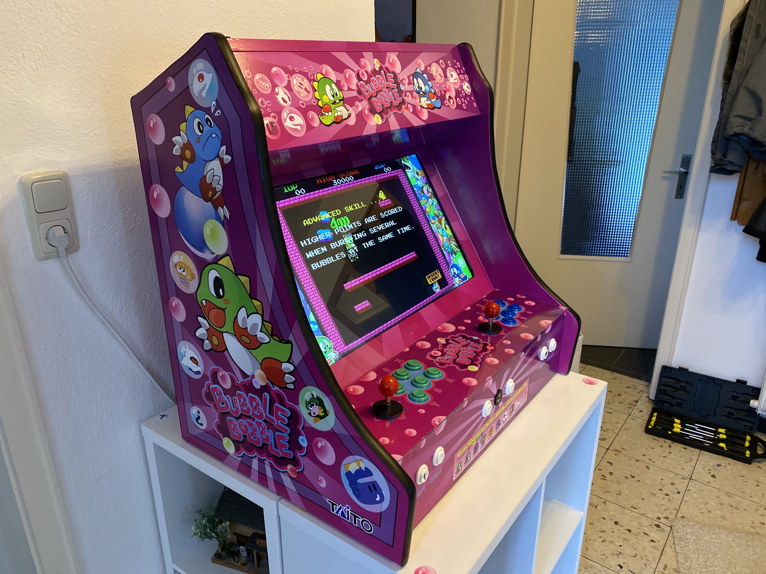
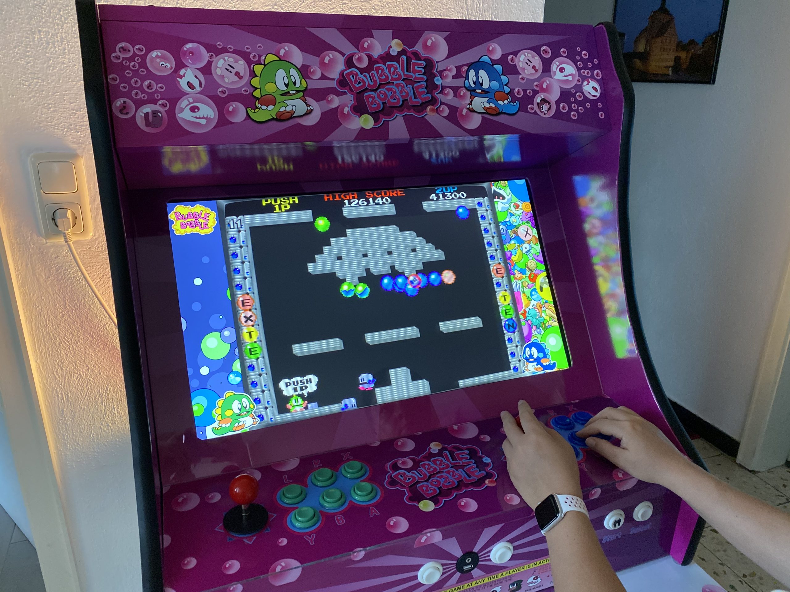
I am really happy how this turned out – especially since with everything that required actual work with hands I am a hopeless case. With this somehow everything worked out.

I still employ the idea of a vertical shoot-em-up centered version… but maybe some day.

If you got any questions or feedback let me know!

So, we’re building something

For some weeks now I am working on the design of something that is being built within the next couple of weeks out of wood and metal (and electronics).

It’s hopefully going to be as nice as I dream it up… What could it be?

I did this design based upon some pixel-material and pictures I’ve gathered around the internets – and took a lot of inspiration from them.

Although I had to create everything in vectors from those small pixel templates… But now everything above is going to be printed on vinyl in glorious vectors – no pixeljunk.

RaspberryPis to Access Points!

Current generations of RaspberryPi single board computers (from 3 up) already got WiFi on-board. Which is great and can be used, in combination with the internal ethernet or even additional network interfaces (USB) to create a nice wired/wireless router. This is what this RaspAP project is about:

This project was inspired by a blog post by SirLagz about using a web page rather than ssh to configure wifi and hostapd settings on the Raspberry Pi. I began by prettifying the UI by wrapping it in SB Admin 2, a Bootstrap based admin theme. Since then, the project has evolved to include greater control over many aspects of a networked RPi, better security, authentication, a Quick Installer, support for themes and more. RaspAP has been featured on sites such as InstructablesAdafruitRaspberry Pi Weekly and Awesome Raspberry Pi and implemented in countless projects.

also on Github: https://github.com/billz/raspap-webgui

This really is going to be very useful while on travels. I plan to replace my GL-INET router, which shows signs of age.

more small projectors coming

Good news everyone!

There are new micro-projectors coming and they are looking good. After the first availability of really small and low-power but enough-light LED projectors (see here) manufacturers have apparently added a laser to the equation.

It is said that…

Unlike traditional projectors that constantly need to be focussed, the Nebra AnyBeam picture is always perfect. You can project onto curved or irregular surfaces with ease – perfect if you want to use it on the fly, or if you want to try your hand at a bit of projection mapping!

This thing will be available, according to the Kickstarter, as a all-in-one package with power and HDMI inputs. It’s got 720p inputs. Well. Well really?

And it will be available to the maker market as a RaspberryPi Hat…

bringing the thinclient back

I had to solve a problem. The problem was that I did not wanted to have the exact same session and screen shared across different work places/locations simultaneously. From looking at the same screen from a different floor to have the option to just walk over to the lab-desk solder some circuits together and have the very same documents opened already and set on the screens over there.

One option was to use a tablet or notebook and carry it around. But this would not solve the need to have the screen content displayed on several screens simultaneously.

Also I did not want to rely on the computing power of a notebook / tablet alone. Of course those would get more powerful over time. But each step would mean I would have to purchase a new one.

Then in a move of desperation I remembered the “old days” when ThinClients used to be the new-kid in town. And then I tried something:

I just recently had moved all house server infrastructure over to Linux and Docker. So what would keep me from utilizing the computing power of that one beefy server in the basement to host all of my desktop needs?

It turns out: Nothing really. Docker is well prepared to host desktop environments. With a bit of tweaking and TigerVNC Xvnc I was able to pre-configure the most current Ubuntu to start my preferred Mate desktop environment in a container and expose it through VNC.

If you wanted to replicate this I would recommend this repository as a starting point.

Even better I found that the RaspberryPi single board computers come with a free pre-licensed and accelerated version of RealVNC.

So I took one of those RaspberryPis, booted up the Raspbian Desktop lite and connected to the dockers VNC port. It all worked just like that.

this is the RaspberryPi client with the windowed docker container VNC session

The screenshot above holds an additional information for you. I wanted sound! Video works smooth up to a certain size of the moving video – after all those RaspberryPis only come with sub Gbit/s wired networking. But to get sound working I had to add some additional steps.

First on the RaspberryPI that you want to output the sound to the speakers you need to install and set-up pulseaudio + paprefs. When you configure it to accept audio over the network you can then configure the client to do so.

In the docker container a simple command would then redirect all audio to the network:

pax11publish -e -S thinclient

Just replace “thinclient” with the ip or hostname of your RaspberryPI. After a restart Chrome started to play audio across the network through the speakers of the ThinClient.

Now all my screens got those RaspberryPIs attached to them and with Docker I can even run as many desktop environments in parallel as I wish. And because VNC does not care about how many connections there are made to one session it means that I can have all workplaces across the house connected to the same screen seeing the same content at the same time.

And yes: The UI and overall feel is silky smooth. And since VNC adapts to some extend to the available bandwidth by changing the quality of the image even across the internet the VNC sessions are very much useable. Given that there’s only 1 port for video and 1 port for audio it’s even possible to tunnel those sessions across to anywhere you might need them.

LED projector for your home automation needs

In 2017 Texas Instruments had released a line of cheap industry grade LED projectors meant to be used in production lines and alike:

DLP® LightCrafter Display 2000 is an easy-to-use, plug-and-play evaluation platform for a wide array of ultra-mobile and ultra-portable display applications in consumer, wearables, industrial, medical, and Internet of Things (IoT) markets. The evaluation module (EVM) features the DLP2000 chipset comprised of the DLP2000 .2 nHD DMD, DLPC2607 display controller and DLPA1000 PMIC/LED driver. This EVM comes equipped with a production ready optical engine and processor interface supporting 8/16/24-bit RGB parallel video interface in a small-form factor.

Texas Instruments

And of course this got picked up by the makers. In the hands of people like MickMake who designed an adapter PCB for the RaspberryPi Zero W to the smallest projector available from TI.

After I had learned about the existence of those small projectors I had to get a couple and try for myself. There would be so many immediate and potential applications in our house.

2x DLPLDCR2000EVM with MickMake adapter and RaspberryPi Zero W

After having them delivered I did the first trial with just a breadboard and the Raspberry Pi 3.

first light!

The projector module has a native resolution of 640×360 – so not exactly high-pixel-density. And of course if the image is projected bigger the screen-door effect is quite noticeable. Also it’s not the brightest of images depending on the size. For the usual use-cases the brightness is definitely sufficient.

Downsides

  • too low brightness for large projection size – no daylight projection
  • low resolution is an issue for text and web content – it is not so much of an issue for moving pictures as you might think. Video playback is well usable.
  • flimsy optics that you need to set focus manually – works but there is no automatic focus or alike.

Upsides

  • very low powered – 2.5A/5V USB power supply is sufficient for Pi Zero + Projector on full brightness (30 lumen)
  • low brightness is not always bad – one of our specific use cases requires an as dim as possible image with fine grain control of thr brightness which this projector has.
  • extremely small footprint / size allows to integrate this device into places you would not have thought of.
  • almost fully silent operation – the only moving part that makes a sound is the color wheel inside the DLP module. You have to put your ear right onto it to hear anything.
  • passive cooling sufficient – even at full brightness an added heat sink is enough to dissipate the heat generated by the LED.

So what are these use cases that require such a projector you ask?

Night status display:

For the last 20+ years I am used to sleep with a “night playlist” running. So far a LED TV was used at the lowest brightness possible. Still it was pretty bright. The projector module allows to dim the brightness down to almost “moon brightness” and also allows to adjust the color balance towards the reds. This means: the perfect night projection is possible! And the power consumption is extremely low. A well watchable lowest brightness red-shifted image also means much lower temperatures on the projector module – it’s crazy how low powered, low temperature.

at 75% brightness (camera did not properly focus…)

Season Window Projection:

Because the projector is small, low-powered and bright enough for back-lit projection we tried and succeeded with a Halloween window projection scene the last season.

outside view
inside view

It really looks funky from the outside – funky enough to have several people stop in front of the house and point fingers. All that while power consumption was really

House overall status projections:

When projecting information is that cheap and power efficient it really shines when used to display overall status information like house-alarm status, general switch maps, locations of family members and so on. I’ve left those to your imagination as these kind of status displays are more or less giving away a lot of personal information that isn’t well suited for the internet.

How to weigh your cat! – the IoT version

This is Leela. She is a 7 year old lilac white British short hair cat that lives with us. Leela had a sister who used to live with us as well but she developed a heart condition and passed away last year. Witnessing how quickly such conditions develop and evaluate we thought that we can do something to monitor Leelas health a bit to just have some sort of pre-alert if something is changing.

Kid in a Candystore

As this Internet of Things is becoming a real thing these days I found myself in a candy store when I’ve encountered that there are a couple of really really cheap options to get a small PCB with input/output connectors into my house WiFi network.

One of the main actors of this story is the so called ESP8266. A very small and affordable system-on-a-chip that allows you to run small code portions and connect itself to a wireless network. Even better it comes with several inputs that can be used to do all sorts of wonderful things.

And so it happened that we needed to know the weight of our cat. She seemed to get a bit chubby over time and having a point of reference weight would help to get her back in shape. If you every tried to weigh a cat you know that it’s much easier said than done.

The alternative was quickly brought up: Build a WiFi-connected scale to weigh her litter box every time she is using it. And since I’ve recently bought an evaluation ESP8266 I just had to figure out how to build a scale. Looking around the house I’ve found a broken human scale (electronics fried). Maybe it could be salvaged as a part donor?

A day later I’ve done all the reading on that there is a thing called “load-cell”. Those load cells can be bought in different shapes and sizes and – when connected to a small ADC they deliver – well – a weight value.

I cracked the human scale open and tried to see what was broken. It luckily turned out to have completely fried electronics but the load-cells where good to go.

Look at this load cell:

Hardware

That brought down the part list of this project to:

  • an ESP8266 – an Adafruit Huzzah in my case
  • a HX711 ADC board to amplify and prepare the signal from the load-cells
  • a human scale with just enough space in the original case to fit the new electronics into and connect everything.

The HX711 board was the only thing I had to order hardware wise – delivered the next day and it was a matter of soldering things together and throwing in a small Arduino IDE sketch.

My soldering and wiring skills are really sub-par. But it worked from the get-go. I was able to set-up a small Arduino sketch and get measurements from the load-cells that seemed reasonable.

Now the hardware was all done – almost too easy. The software would be the important part now. In order to create something flexible I needed to make an important decision: How would the scale tell the world about it’s findings?

Software

Two basic options: PULL or PUSH?

Pull would mean that the ESP8266 would offer a webservice or at least web-server that exposes the measurements in one way or the other. It would mean that a client needs to poll for a new number in regular intervals.

Push would mean that the ESP8266 would connect to a server somewhere and whenever there’s a meaningful measurement done it would send that out to the server. With this option there would be another decision of which technology to use to push the data out.

Now a bit of history: At that time I was just about to re-implement the whole house home automation system I was using for the last 6 years with some more modern/interoperable technologies. For that project I’ve made the decision to have all events (actors and sensors) as well as some additional information being channeled into MQTT topics.

Let’s refer to Wikipedia on this:

“MQTT1 (formerly MQ Telemetry Transport) is an ISO standard (ISO/IEC PRF 20922) publish-subscribe-based “lightweight” messaging protocol for use on top of the TCP/IP protocol. It is designed for connections with remote locations where a “small code footprint” is required or the network bandwidth is limited. The publish-subscribe messaging pattern requires a message broker. Thebroker is responsible for distributing messages to interested clients based on the topic of a message. Andy Stanford-Clark and Arlen Nipper of Cirrus Link Solutions authored the first version of the protocol in 1999.”

Something build for oil-pipelines can’t be wrong for your house – can it?

So MQTT uses the notation of a “topic” to sub-address different entities within it’s network. Think of a topic as just a simple address like “house/litterbox/weight”. And with that topic MQTT allows you to set a value as well.

The alternative to MQTT would have been things like WebSockets to push events out to clients. The decision for the home-automation was done towards MQTT and so far it seems to have been the right call. More and more products and projects available are also focussing on using MQTT as their main message transport.

For the home automation I had already set-up a demo MQTT broker in the house – and so naturally the first call for the litterbox project was to utilize that.

The folks of Adafruit provide the MQTT library with their hardware and within minutes the scale started to send it’s measurements into the “house/litterbox/weight” topic of the house MQTT broker.

Some tweaking and hacking later the litterbox was put together and the actual litterbox set on-top.

Since Adafruit offers platform to also send MQTT messages towards and create neat little dashboards I have set-up a little demo dashboard that shows a selection of data being pushed from the house MQTT broker to the Adafruit.io MQTT broker.

These are the raw values which are sent into the weight topic:

You can access it here: https://io.adafruit.com/bietiekay/stappenbach

So the implementation done and used now is very simple. On start-up the ESP8622 initialises and resets the weight to 0. It’ll then do frequent weight measurements at the rate it’s configured in the source code. Those weight measurements are being monitored for certain criteria: If there’s a sudden increase it is assumed that “the cat entered the litterbox”. The weight is then monitored and averaged over time. When there’s a sudden drop of weight below a threshold that last “high” measurement is taken as the actual cat weight and sent out to a /weight topic on MQTT. The regular measurements are sent separately to also a configurable MQTT topic.

You can grab the very ugly source code of the Arduino sketch here: litterbox_sourcecode

And off course with a bit of logic this would be the calculated weight topic:

Of course it is not enough to just send data into MQTT topics and be done with it. Of course you want things like logging and data storage. Eventually we also wanted to get some sort of notification when states change or a measurement was taken.

MQTT, the cloud and self-hosted

Since MQTT is enabling a lot of scenarios to implement such actions I am going to touch just the two we are using for our house.

  1. We wanted to get a push notification to our phones whenever a weight measurement was taken – essentially whenever the cat has done something in the litterbox. The easiest solution: Set-Up a recipe on If This Than That (IFTTT) and use PushOver to send out push notifications to whatever device we want.
  2. To log and monitor in some sort of a dashboard the easiest solution seemed to be Adafruits offer. Of course hosted inside our house a combination of InfluxDB to store, Telegraf to gather and insert into InfluxDB and Chronograf to render nice graphs was the best choice.

Since most of the above can be done in the cloud (as of: outside the house with MQTT being the channel out) or inside the house with everything self-hosted. Some additional articles will cover these topics on this blog later.

There’s lots of opportunity to add more logic but as far as our experiments and requirements go we are happy with the results so far – we now regularly get a weight and the added information of how often the cat is using her litterbox. Especially for some medical conditions this is quite interesting and important information to have.

a new Music Service for SONOS: xenim streaming network

I am a frequent podcast live-stream listener. And being that I am enjoying the awesome service called xenim streaming network.

Bildschirmfoto 2014-08-19 um 21.03.21

Any Podcast producer can join the xsn and with that can live-stream his own Podcast while recording. It’s CDN is based on voluntarily provided resources and pretty rock-solid as far as my experience with it goes.

Since I am a frequent user of this – and I’ve got that gorgeous SONOS hardware scattered around my house – I thought I need to have that service integrated into my SONOS set.

The SONOS system knows the concept of “Music Services”. There are quite a lot of them but xsn is missing. But SONOS is awesome and they got an API!

Unfortunately the API documentation is hidden behind a NDA wall so that would be a no-go. What’s not hidden is what the SONOS controllers have to discuss with all the existing services. Most of the time these do not use HTTPS so we’re free to listen to the chatters. I did just that and was able, for the sake of interoperability, to reverse engineer the SONOS SMAPI as far as it is necessary to make my little xsn Music Service work.

As usual you can get the source-code distributed freely through Github. If you’re not into that sort of compiling and programming things, you are invited to use my free-of-charge provided service. To set it up on your home SONOS just follow these simple steps:

Step 1: Start your SONOS Controller Application and find out the IP address of your SONOS.

Click on “About My Sonos System” and check the IP address written next to the “Associated ZP”.

Screen Shot 2014-08-19 at 19.45.56

Step 2: Add the xsn Music Service.

By opening a browser window and browsing to: http://<your-associated-zp-ip>:1400/customsd.htm

When you’re there – fill out the fields as below. The SID is either 255, or if you used that previously, something between 240-253. The service name is “xenim streaming network”. The Endpoint URL and Secure Endpoint URL both are http://xsn.schrankmonster.de/xsn

Set the Polling interval to 30 seconds. Click on the Anonymous Authentication SOAP header policy and you’re good to go. Click on “send” to finish.

Bildschirmfoto 2014-08-19 um 21.16.27

Step 3: Add the new Music Service to your SONOS Controller.

Click on “Add Music Services” and click through until you see “xenim streaming network”. Add the service and you’re set!

p.s.: It’s normal that the service icon is a question mark.

Step 4: Enjoy Live Podcasts!

Source 1: https://github.com/bietiekay/sonos-xsn-service
Source 2: http://streams.xenim.org/

How to get a list of all recent Podcasts on SONOS

I am using an external podcast download tool to stay updated on all podcasts I subscribed to. For this purpose SubSonic is a good choice – actually for a lot more also.

Screen Shot 2014-07-02 at 18.56.52

One of the quirks of the SONOS products is that Podcasts are not really well supported. In fact there is no support at all.

So I wrote a tool that extends the SONOS players with the functionality to “remember” play positions within audiobooks and podcasts. Now what’s left to properly have podcasts supported is a view of the most recently updated podcasts. Wouldn’t it be nice to have a “Folder View” in the SONOS controller of what’s new across all the different podcasts you are subscribed to?

Now here’s the trick:

Use a small script on any RaspberryPi in the house to dynamically create hardlinks to the podcasts files in a “Recently Updated Podcasts” folder.

The script is something like this:

find /where-your-podcasts-are/ -type f -printf ‘%TY-%Tm-%Td %TT %p\n’ | sort | tail -n 25 | cut -c 32- | sed -e “s/^/ln \”/” -e “s/$/\”/” -e “s/$/ \”\/recentPodcasts\/\”/” | sh

This short line will go through all folders and subfolders in /where-your-podcasts-are/ and then create Hardlinks in /recentPodcasts to the most recent 25 files.

That way, and when /recentPodcasts/ is made accessible to your SONOS controllers, you’ll have something like this:

Screen Shot 2014-07-02 at 19.17.24

Source 1: http://www.subsonic.org
Source 2: play position bookmarker

Boblight Alternative: Hyperion

After setting up Boblight on two TVs in the house – one with 50 and one with 100 LEDs – I’ve used it for the last 5 months on a daily basis almost.

First of all now every screen that does not come with “added color-context” on the wall seems off. It feels like something is missing. Second of all it has made watching movies in a dark room much more enjoyable.

The only concerning factor of the past months was that the RaspberryPi does not come with a lot of computational horse-power and thus it has been operating at it’s limits all the time. With 95-99% CPU usage there’s not a lot of headroom for unexpected bitrate spikes and what-have-you.

So from time to time the Pis where struggling. With 10% CPU usage for the 50 LEDs and 19% CPU usage for the 100 LEDs set-up there was just not enough CPU power for some movies or TV streams in Full-HD.

Hyperion

So since even overclocking only slightly improved the problem of Boblight using up the precious CPU cycles for a fancy light-show I started looking around for alternatives.

“Hyperion is an opensource ‘AmbiLight’ implementation controlled using the RaspBerry Pi running Raspbmc. The main features of Hyperion are:

  • Low CPU load. For a led string of 50 leds the CPU usage will typically be below 1.5% on a non-overclocked Pi.
  • Json interface which allows easy integration into scripts.
  • A command line utility allows easy testing and configuration of the color transforms (Transformation settings are not preserved over a restart at the moment…).
  • Priority channels are not coupled to a specific led data provider which means that a provider can post led data and leave without the need to maintain a connection to Hyperion. This is ideal for a remote application (like our Android app).
  • HyperCon. A tool which helps generate a Hyperion configuration file.
  • XBMC-checker which checks the playing status of XBMC and decides whether or not to capture the screen.
  • Black border detector.
  • A scriptable effect engine.
  • Generic software architecture to support new devices and new algorithms easily.

More information can be found on the wiki or the Hyperion topic on the Raspbmc forum.”

Especially the Low CPU load did raise interest in my side.

Setting Hyperion up is easy if you just follow the very straight-forward Installation Guide. On Raspbmc the set-up took me 2 minutes at most.

If you got everything set-up on the Pi you need to generate a configuration file. It’s a nice JSON formatted config file that you do not need to create on your own – Hyperion has a nice configuration tool. Hypercon:

Screen Shot 2014-06-28 at 08.52.51

So after 2 more minutes the whole thing was set-up and running. Another 15 minutes of tweaking here and there and Hyperion replaced Boblight entirely.

What have I found so far?

  1. Hyperions network interfaces are much more controllable than those from Boblight. You can use remote clients like on iPhone / Android to set colors and/or patterns.
  2. It’s got effects for screen-saving / mood-lighting!
  3. It really just uses a lot less CPU resources. Instead of 19% CPU usage for 100 LEDs it’s down to 3-4%. That’s what I call a major improvement
  4. The processing filters that you can add really add value. Smoothing everything so that you do not get bright flashed when content flashes on-screen is easy to do and really helps with the experience.

All in all Hyperion is a recommended replacement for boblight. I would not want to switch back.

Source 1: Setting up Boblight
Source 2: https://github.com/tvdzwan/hyperion/wiki/Installation

using the RaspberryPi to make all SONOS speakers support Apple Airplay

Airplay allows you to conveniently play music and videos over the air from your iOS or Mac OS X devices on remote speakers.

Since we just recently “migrated” almost all audio equipment in the house to SONOS multi-room audio we were missing a bit the convenience of just pushing a button on the iPad or iPhones to stream audio from those devices inside the household.

To retrofit the Airplay functionality there are two options I know of:

1: Get Airplay compatible hardware and connect it to a SONOS Input.

airportexpress_2012_back-285111
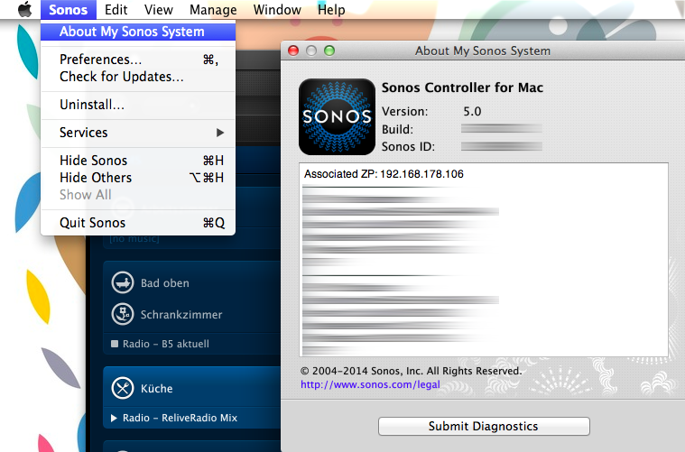
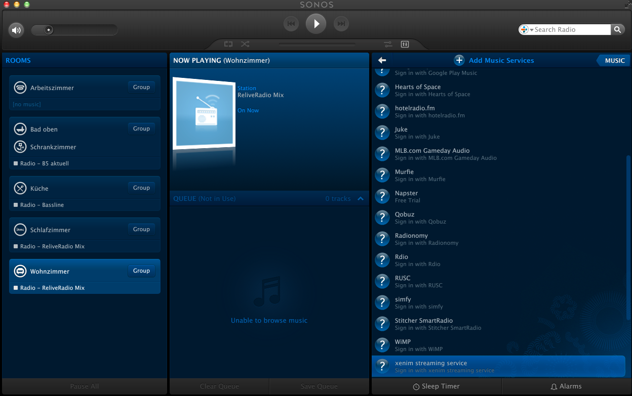
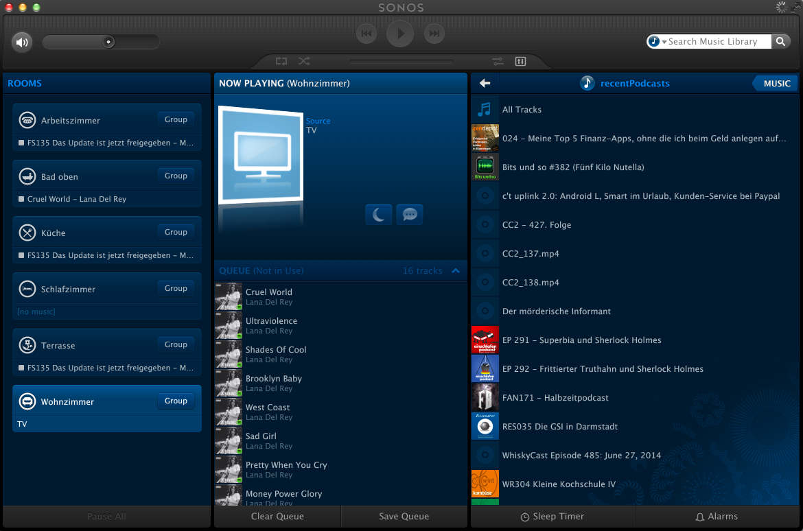
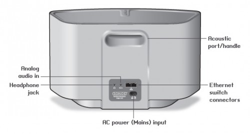
You have to get Airplay hardware (like the Airport Express/Extreme,…) and attach it physically to one of the inputs of your SONOS Set-Up.  Typically you will need a SONOS Play:5 which has an analog input jack.

PLAY5_back

2: Set-Up a RaspberryPi with NodeJS + AirSonos as a software-only solution

You will need a stock RaspberryPi online in your home network. Of course this can run on virtually any other device or hardware that can run NodeJS. For the Pi setting it up is a fairly straight-forward process:

You start with a vanilla Raspbian Image. Update everything with:

sudo apt-get update

sudo apt-get upgrade

Then install NodeJS according to this short tutorial. To set-up the AirSonos software you will need to install additional avahi software. Especially this was needed for my install:

sudo apt-get install git-all libavahi-compat-libdnssd-dev

You then need to get the AirSonos software:

sudo npm install airsonos -g

After some minutes of wait time and hard work by the Pi you will be able to start AirSonos.

sudo airsonos

And it’ll come up with an enumeration of all active rooms.

Screen Shot 2014-06-25 at 11.38.47

And on all your devices it’ll show up like this:

IMG_1046

and

Screen Shot 2014-06-25 at 12.38.27


Source: https://github.com/stephen/airsonos

weave your net of things that have internet…ehm – internet of things

node-red-screenshot

The internet of things” is a buzzword used more and more. It means that things around you are connected to the (inter)network and therefore can talk to each other and, when combined, offer fantastic new opportunities.

Yeah right.

So NodeRed is a NodeJS based toolset that allows you to create so called “flows” (see picture above). Those flows determine what reacts and happens when things happen. Fantastic, told you!

Source 1: http://nodered.org/
Source 2: http://en.wikipedia.org/wiki/Internet_of_ThingsSource 3: http://nodejs.org/

How to fix a mono CS0589 Internal compiler error during parsingSystem.FormatException error on the RaspberryPi

When you want to compile some C# code using MONO on Linux on your RaspberryPi and you encounter this strange error message:

error CS0589: Internal compiler error during parsingSystem.FormatException

You need to do:

  1. Update your Debian by running:

    sudo apt-get upgrade
    sudo apt-get update

  2. Upgrade your RaspberryPi firmware:

    sudo rpi-update

  3. Reboot your RaspberryPi
  4. Retry compiling – should work now.

The reason for Mono to crap out like above: Previous Mono versions and RaspberryPi firmwares where not compatible due to one side using HardFP and the other not.

How to install NodeJS and NPM on the RaspberryPi without getting “Illegal Instruction” error messages

I tried a couple of times to compile NodeJS on the RaspberryPi and failed miserably. It not only takes ages to compile NodeJS on the Pi. After the successful compile and install run most of the time running it just results in an error message “Illegal Instruction” or “Ungültiger Maschinencode”.

Now there’s a pretty easy way to do that on your own. Run these commands:

wget http://node-arm.herokuapp.com/node_latest_armhf.deb

After the download is finished successfully you can install it by running this as root:

sudo dpkg -i node_latest_armhf.deb

This will have installed a relatively new NodeJS built as well as NPM on your RaspberryPi. Don’t panic when NPM is slower than you would expect… just be patient.

Enjoy!